Composite Stiffener & Rib Tooling Design Guide | MDC Mould

Master composite stiffener tooling design with MDC Mould. Learn rib draft angles, fillet radii, hat stiffeners, and compression mold action for panels.

Thin composite skins can achieve impressive structural performance, but their efficiency does not come from thickness alone. In many lightweight structures, ribs, stringers and other stiffening features are used to increase bending stiffness, delay buckling and provide more efficient load paths without adding unnecessary material.

For composite manufacturers, however, adding a stiffener is not simply a structural design decision. Every rib height, spacing, intersection, radius and attachment surface also changes how the component must be manufactured. This is where composite stiffener tooling becomes an important part of the engineering process.

Composite Stiffener 2

Why Reinforced Composite Structures Need More Than a Thin Skin

A flat or gently curved composite panel may have high specific strength, but a thin panel can still be vulnerable to out-of-plane deformation and local buckling under compression, bending or shear. Increasing the skin thickness can improve stiffness, but it also increases material consumption and mass.

A more efficient approach is to introduce structural reinforcement. A stiffener increases the effective section depth of the structure and divides a large flexible panel into smaller supported regions. Depending on the loading condition, the reinforcement may take the form of ribs, stringers, hat sections, T-sections, J-sections or other engineered profiles.

The engineering objective is therefore not simply to make the structure thicker. It is to place material where it contributes most effectively to stiffness and load transfer.

Structural reinforcement changes the load path

When a reinforced composite panel is loaded, the skin and stiffener do not work as completely independent components. Their interaction determines how forces are transferred through the structure. A properly designed configuration can allow the skin to carry distributed loads while the stiffeners provide additional resistance to bending and local instability.

This interaction is particularly important in lightweight structures where designers are trying to obtain high stiffness without relying on a large increase in material thickness.

Stiffener Geometry Is a Manufacturing Decision as Well as a Structural Decision

In a reinforced composite component, the shape of the stiffener directly affects tooling requirements. A theoretically efficient cross-section may become difficult to form, difficult to demould or difficult to control dimensionally.

For this reason, structural design and tooling design should be evaluated together rather than sequentially.

Design FeatureStructural RoleTooling Consideration
Stiffener heightImproves section stiffness and buckling resistanceInfluences cavity depth, demoulding and tool rigidity
Stiffener spacingControls unsupported skin areaAffects mold layout, heating and local forming behavior
Flange widthProvides a larger load-transfer areaRequires stable forming surfaces and dimensional control
Corner radiusReduces local stress concentrationAffects material flow, fiber conformity and tool machining
Intersection geometryControls load transfer between ribsCan create local thickness and forming challenges
Draft directionUsually has limited direct structural influenceCan determine whether the finished part can be released reliably

This is why a composite structure mould should be developed with the actual part geometry, material system and production process in mind rather than treated as a simple negative representation of the CAD model.

Common Stiffener Profiles and What They Mean for Tooling

Different stiffener cross-sections provide different combinations of stiffness, weight, manufacturability and connection area. There is no universally optimal profile. The appropriate geometry depends on loading, available space, material architecture and the selected manufacturing route.

Rectangular and blade-type stiffeners

Simple stiffener geometries are relatively straightforward from a tooling perspective. They can be useful where the reinforcement mainly needs to increase local bending stiffness without introducing complicated three-dimensional intersections.

Their simplicity can also make them attractive for early-stage tooling development, especially when dimensional repeatability is more important than achieving the most structurally efficient cross-section.

T-shaped stiffeners

T-sections can provide an efficient increase in section stiffness while maintaining a defined flange area for connection with the surrounding skin.

From a tooling perspective, the junction between the vertical web and flange requires particular attention. Local radii, material placement and release direction should be evaluated before the final tool geometry is frozen.

Hat and omega-shaped stiffeners

Hat-shaped or omega-type reinforcement is widely associated with lightweight panel construction because the closed-like profile can provide useful stiffness without simply increasing skin thickness.

However, the more complex profile also introduces additional forming surfaces. Tool design therefore needs to consider material draping, local compaction, corner radii and demoulding access.

J- and I-type structures

J- and I-type sections can be selected where higher structural efficiency or specific attachment conditions justify a more complicated profile. Their geometry generally places greater demands on tooling accuracy because several surfaces must remain dimensionally coordinated after molding.

Rib Layout: Why One-Directional and Grid Reinforcement Behave Differently

The performance of a reinforced composite panel depends not only on the cross-section of each stiffener but also on how the reinforcement is distributed across the panel.

Unidirectional stiffener layouts

Parallel ribs or stringers are useful when the dominant load direction is relatively clear. The reinforcement can be concentrated along the primary load path while the skin handles the distributed portion of the load.

From the tooling perspective, repeated parallel features can simplify manufacturing compared with a highly interconnected grid. However, consistency between individual ribs becomes important because dimensional variation can change local stiffness and assembly conditions.

Grid-reinforced structures

Crossed ribs can distribute loads in multiple directions and provide support across a larger panel area. Depending on the structural objective, rectangular, triangular or hexagonal patterns may be considered.

The intersections are often more difficult than the straight rib sections. Multiple material paths meet at the same location, creating potential changes in local thickness, compaction and fiber orientation.

Therefore, composite rib tooling for grid structures needs to address the intersection geometry rather than focusing only on the individual rib profile.

Why Stiffener Intersections Are Difficult to Manufacture

A straight stiffener may be relatively predictable. An intersection is different because several structural features converge within a small region.

If material accumulates around the intersection, local thickness can increase. If fibers cannot conform properly to the tool surface, gaps or bridging may develop. If the material cannot compact uniformly, the local mechanical properties may differ from the surrounding structure.

These issues are not purely material problems. They can originate from the relationship between part geometry, charge or preform placement, mold surface geometry and the selected forming process.

Tooling response

  • Use appropriate transition radii at stiffener intersections.
  • Avoid unnecessary abrupt changes in section geometry.
  • Provide sufficient access for material placement where required.
  • Evaluate local compaction and material flow before finalizing the mold.
  • Consider inspection access for critical structural regions.

In complex reinforced structures, a small change in intersection geometry can sometimes make the difference between a robust production process and a difficult molding operation.

Material Placement and Tool Geometry Must Work Together

Reinforced composite structures often contain significant changes in thickness and geometry. The tooling therefore has to support controlled material placement rather than simply reproduce the external surface.

For compression-based processes, charge size, charge position and charge distribution can influence how material moves during closing. A poorly planned charge configuration may result in uneven filling, fiber movement or local excess material.

This becomes particularly important when the component contains several ribs or deep stiffener sections. The material has to reach the required regions while maintaining acceptable fiber distribution and avoiding excessive disturbance of the designed reinforcement architecture.

As a result, tooling development should consider the relationship between:

  • part geometry;
  • stiffener location;
  • material architecture;
  • charge or preform arrangement;
  • mold closing behavior;
  • venting requirements;
  • compaction conditions;
  • demoulding sequence.

Tool Rigidity Matters More When the Part Contains Deep Ribs

A reinforced composite part may have relatively thin walls but a surprisingly complex three-dimensional mold surface. Deep ribs and local projections can generate uneven loading on the tooling system during forming.

If the mold structure is not sufficiently rigid, local deflection can influence part thickness, dimensional accuracy and the consistency of the parting interface.

This is one reason why tooling design cannot be based only on the nominal cavity surface. The supporting structure behind the working surface must also be considered.

Key tooling considerations include:

  • working-surface thickness;
  • backing structure;
  • support ribs and reinforcement;
  • clamping conditions;
  • load distribution;
  • thermal expansion;
  • machining accuracy;
  • tool alignment.

For larger composite components, these factors become increasingly important because a small local displacement can influence a much larger finished surface.

Demoulding Becomes a Design Constraint for Reinforced Parts

A reinforced composite structure can be structurally efficient but difficult to release from the mold. Deep ribs, undercuts and enclosed profiles can restrict the available demoulding direction.

Therefore, draft and release strategy should be considered during part design rather than after the mold has already entered manufacturing.

The tooling team may need to evaluate whether a feature can be released in a single direction or whether a more complex tooling configuration is required.

This is particularly relevant to ribbed structures where several stiffeners intersect or where the reinforcement extends around curved surfaces.

Good demoulding design can reduce production risk

A practical mold should allow the finished component to be removed without excessive mechanical force. This helps protect both the part and the tooling surface and can improve repeatability over long production runs.

Composite Stiffener

Surface Accuracy Is Not Only an Appearance Issue

For many composite components, the mold surface determines much more than visual quality. Surface geometry can affect assembly interfaces, aerodynamic or hydrodynamic profiles, sealing areas and dimensional relationships between the reinforced panel and adjacent components.

Stiffened structures are particularly sensitive because several geometric features must remain coordinated. A rib that is slightly misplaced or a flange that varies in height can create downstream assembly problems even when the main skin appears acceptable.

Consequently, precision machining, surface finishing and dimensional inspection should be treated as part of the structural tooling strategy.

Skin-to-Stiffener Connection: The Structural Interface That Tooling Cannot Ignore

In many reinforced composite architectures, the connection between the skin and stiffener is a critical load-transfer region. The structural design may rely on adhesive bonding, co-curing, secondary bonding or another integration method.

Regardless of the selected process, the tooling has to support the required interface geometry.

A flange that is not sufficiently flat, a local mismatch between surfaces or uncontrolled dimensional variation can affect bonding conditions and therefore the overall structural performance.

Tooling should support consistent interface conditions

  • stable flange dimensions;
  • controlled surface geometry;
  • repeatable rib position;
  • appropriate corner transitions;
  • consistent pressure or compaction conditions where applicable;
  • inspection access for critical bonding areas.

In other words, the mold is part of the load-transfer quality chain. It does not carry the operational load of the finished structure, but it helps establish the geometry through which that load must eventually be transferred.

How to Develop Tooling for a Reinforced Composite Part

A practical tooling workflow begins with the structural requirements and ends with production validation. The following sequence can help reduce late-stage design changes.

1. Review the structural geometry

Identify the skin, stiffeners, ribs, flanges, intersections, attachment regions and critical dimensional interfaces. The objective is to understand which features actually control structural performance.

2. Identify the forming process

The tooling concept depends on whether the component will be produced by compression molding, prepreg processing, RTM, infusion, bonding or another composite manufacturing route.

3. Evaluate material placement

Determine how the selected material system can reach the stiffened regions while maintaining the required reinforcement architecture and avoiding excessive material movement.

4. Define parting and release strategy

Establish suitable parting surfaces and demoulding directions before machining begins. Complex rib profiles may require a more carefully engineered release concept.

5. Develop the supporting mold structure

Working surfaces, backing structures and support elements should be designed to maintain dimensional stability under production loads and temperature changes.

6. Manufacture and inspect the tooling

Precision machining is followed by dimensional inspection and surface verification. Critical rib and interface dimensions should receive particular attention.

7. Conduct mold trials

Trial molding provides an opportunity to evaluate filling, material behavior, release, flash, surface quality and dimensional consistency before the tool enters regular production.

Typical Manufacturing Problems in Reinforced Composite Tooling

Observed IssuePossible Tooling-Related CauseEngineering Focus
Incomplete rib formationInsufficient material access or unsuitable forming geometryReview charge/preform arrangement and cavity geometry
Local bridgingSharp transition or unsuitable radiusImprove geometric transition
Uneven rib heightTool deflection or dimensional variationReview mold rigidity and machining accuracy
Excessive flashParting-line mismatch or pressure concentrationImprove parting-line control
Part stickingInsufficient draft or unfavorable release geometryReview demoulding direction and surface condition
Dimensional inconsistencyThermal or structural movement of the toolingEvaluate tool structure and thermal behavior
Intersection defectsLocal material accumulation or poor compactionOptimize intersection geometry and forming strategy

Reinforced Composite Structures Require Structure-Specific Tooling

A reinforced composite component should not be treated as a conventional flat panel with ribs simply added afterward. The reinforcement changes the structural load path, material distribution, forming behavior and tooling architecture at the same time.

This is particularly important for components where low mass and high stiffness are both critical. The tooling must reproduce the intended geometry consistently while accommodating the realities of composite processing.

For manufacturers, the most important question is therefore not simply: “Can this shape be machined?”

A more useful question is: “Can this geometry be molded repeatedly, dimensionally and economically?”

When Should a Composite Tooling Manufacturer Be Involved?

Tooling input is most valuable before the structural geometry is completely frozen. Early collaboration allows potential manufacturing constraints to be identified while changes are still relatively inexpensive.

For reinforced structures, an engineering review may examine:

  • stiffener height and spacing;
  • rib intersection design;
  • draft and release direction;
  • parting-line location;
  • flange and bonding interfaces;
  • material placement feasibility;
  • tool rigidity;
  • thermal behavior;
  • inspection requirements;
  • expected production volume.

Addressing these items during the design stage can reduce the risk of discovering tooling problems only after the mold has been manufactured.

MDC Approach to Composite Structure Tooling

MDC develops composite tooling with attention to the relationship between part geometry and production requirements. For reinforced composite components, this means looking beyond the external skin and evaluating the ribs, stiffeners, interfaces and forming conditions that determine whether the tool can deliver a stable production process.

Depending on the application, tooling development can involve structural mold design, precision machining, parting-line engineering, surface finishing, dimensional inspection and mold trial support.

The objective is not simply to manufacture a mold that matches a CAD file. It is to develop tooling that can reproduce the intended composite structure with consistent geometry throughout production.

FAQ About Reinforced Composite Tooling

What is a reinforced composite structure?

A reinforced composite structure combines a relatively thin composite skin or panel with ribs, stringers, stiffeners or other structural reinforcement. The reinforcement increases stiffness and helps control deformation and buckling without relying entirely on greater skin thickness.

What is composite stiffener tooling?

Composite stiffener tooling refers to molds, tools or tooling systems designed to manufacture composite parts containing structural ribs, stringers or other reinforcement features. The tooling must reproduce both the skin and the stiffener geometry accurately.

Why are stiffener intersections difficult to mold?

Intersections bring several material paths and geometric features together in a limited area. This can create local thickness changes, material accumulation, fiber distortion or compaction challenges. Tool geometry should therefore be developed specifically for the intersection region.

Does stiffener height affect mold design?

Yes. Greater stiffener height can increase structural stiffness, but it can also affect cavity depth, tool rigidity, material placement and demoulding. The structural target and manufacturing requirements should therefore be considered together.

Why is mold rigidity important for reinforced composite parts?

Reinforced parts can generate non-uniform loads across a complex mold surface. Insufficient tool rigidity may contribute to dimensional variation, parting-line mismatch or inconsistent rib geometry.

Can composite stiffeners be manufactured using compression molding?

Compression molding can be used for suitable reinforced composite geometries, depending on the material system, component dimensions and structural requirements. The mold design must account for material placement, flow, pressure, temperature and demoulding conditions.

Conclusion

Reinforcement is one of the most effective ways to increase the structural efficiency of a lightweight composite panel. Ribs and stiffeners can improve stiffness, delay buckling and create efficient load paths while avoiding unnecessary increases in skin thickness.

But the structural benefit of reinforcement ultimately depends on whether the geometry can be manufactured consistently. Stiffener profiles, intersections, material placement, parting lines, tool rigidity and demoulding all become interconnected engineering considerations.

For this reason, the design of reinforced composite structures and the design of their tooling should be considered as two parts of the same manufacturing problem. A well-engineered composite structure mould does more than reproduce the final shape—it provides the dimensional and process foundation required to turn a lightweight structural concept into a repeatable production part.
Precision Composite Mold & Tooling Manufacturer

Custom precision composite molds by MDC Mould. Expert tooling for SMC, BMC, carbon fiber & GMT with 0.03mm shear edges and 4000T in-house tryout presses.

A composite mold is one of the most important components in composite manufacturing. The mold determines the final geometry of the part while also influencing dimensional accuracy, surface quality, material flow, curing behavior, demoulding, and production repeatability.

Unlike a simple forming tool, composite tooling must be designed around the specific material and molding process being used. Carbon fiber composites, SMC, BMC, FRP, and other composite materials can have different flow characteristics, curing requirements, pressure conditions, and temperature requirements.

At MDC, we manufacture customized composite molds and composite tooling for a wide range of industrial applications. Our tooling solutions are developed according to product geometry, composite material, molding process, production volume, equipment conditions, and required surface quality.

What Is a Composite Mold?

A composite mold is a precision tooling system used to form composite materials into a defined product geometry. Depending on the application, composite molds can be used with processes such as compression molding, prepreg molding, RTM, vacuum-assisted processes, and other composite manufacturing methods.

The mold normally consists of one or more forming surfaces together with structural supports, heating components, venting features, locating elements, inserts, and other tooling components required by the production process.

The basic function is straightforward: the mold provides the geometry and surface against which the composite material is formed or cured.

However, achieving stable production requires much more than simply reproducing the product shape. A production-oriented composite mould must also consider:

  • Dimensional accuracy
  • Mould rigidity
  • Thermal stability
  • Material flow
  • Curing behavior
  • Surface finish
  • Venting
  • Demoulding
  • Parting-line control
  • Production cycle requirements
sheet molding compounds

Why Composite Mold Design Matters

Composite parts often contain complex curves, ribs, bosses, deep sections, varying wall thicknesses, or large cosmetic surfaces. These features can create specific challenges during forming and curing.

A well-designed composite mold helps control these challenges by providing a stable and accurately manufactured forming surface.

Poor tooling design can contribute to:

  • Dimensional variation
  • Surface defects
  • Warping
  • Incomplete filling
  • Excessive flash
  • Difficult demoulding
  • Uneven curing
  • Inconsistent part quality

For this reason, mold design should begin with an understanding of the complete manufacturing process rather than being treated as a separate machining task.

Composite Mold Design Starts with the Material and Process

There is no single mold structure suitable for every composite application. The correct tooling configuration depends on the material, forming method, product geometry, production volume, and required performance.

Carbon Fiber Composite Molds

Carbon fiber components may be manufactured using prepreg, compression molding, autoclave, RTM, or other processes. The tooling must be designed according to the selected material system and curing process.

For applications requiring high-quality cosmetic surfaces, cavity accuracy and surface finishing become particularly important because the mold surface can directly influence the finished carbon fiber component.

SMC Composite Molds

SMC molds are commonly used for compression molding applications. The tooling must accommodate material flow, molding pressure, curing temperature, flash control, venting, and demoulding requirements.

For large SMC components, mould rigidity and thermal distribution are especially important for maintaining consistent production results.

BMC Molds

BMC molding also requires tooling designed around thermoset material behavior. Cavity geometry, temperature control, venting, surface finish, and parting-line accuracy can all influence the final molded component.

FRP and Other Composite Molds

FRP and other reinforced composite materials may use different forming and curing processes. The mould structure should therefore be adapted to the selected manufacturing method, material system, and production requirements.

Key Elements of a Composite Mold

A production-ready composite mold typically consists of several interconnected engineering features. Each component contributes to the performance of the overall tooling system.

Mould Cavity

The cavity defines the external or internal geometry of the molded component. Accurate machining is essential for maintaining the required product dimensions and surface characteristics.

Mould Core

For components with enclosed or hollow geometries, the core forms the corresponding internal surface. Core positioning and alignment must be controlled carefully to maintain consistent wall thickness.

Parting Surface

The parting surface determines how the mould sections separate and can have a significant effect on flash control and demoulding.

A precise parting line helps minimize unwanted material leakage and can reduce secondary trimming work.

Heating System

For thermoset composite molding processes, heating can be essential for controlling material flow and curing. The heating configuration should provide suitable thermal conditions across the mould rather than creating excessive local temperature differences.

Venting System

Venting provides pathways for trapped air and gases to escape during molding. Vent locations should be considered according to material flow and cavity geometry.

Supporting Structure

The supporting structure provides the rigidity required to maintain mould geometry during molding. This becomes particularly important for large-format composite tooling and applications involving repeated pressure and thermal cycles.

Surface Finish of Composite Molds

Surface finish is one of the most visible aspects of composite tooling because the mould surface can be transferred directly to the finished part.

For cosmetic composite components, surface quality may be a critical acceptance requirement. Machining marks, scratches, local steps, or inconsistent polishing can potentially appear on the molded surface.

The typical finishing process may include:

  • Precision CNC machining
  • Grinding
  • Manual fitting
  • Surface correction
  • Polishing
  • Final visual inspection

The required finish should be defined according to the intended product surface rather than applying the same polishing specification to every composite mold.

Dimensional Accuracy and Stability in Composite Tooling

Dimensional accuracy is fundamental to composite mold performance. The mould must maintain the designed geometry while exposed to mechanical loads, temperature changes, and repeated production cycles.

Large composite tooling can be particularly sensitive to structural deformation and thermal expansion. For this reason, mould design should consider both the geometry of the cavity and the supporting structure behind it.

Mould Rigidity

Adequate structural rigidity helps prevent unwanted deformation during molding. A rigid tooling system provides a more stable reference for the composite material during forming and curing.

Thermal Stability

Temperature changes can cause tooling materials to expand or contract. The effects become more important as mould dimensions increase or when the process operates at elevated temperatures.

Shrinkage Compensation

Composite materials can experience dimensional changes during curing and cooling. Tooling design may therefore need to account for expected material behavior so that the final part meets the required dimensions.

Heating and Temperature Control in Composite Moulding

For thermoset composite processes, temperature is closely related to material flow and curing. A suitable composite mould should therefore provide stable thermal conditions appropriate for the selected material and process.

Uneven temperature distribution may contribute to:

  • Uneven curing
  • Surface variation
  • Dimensional instability
  • Residual stress
  • Local warpage
  • Cycle-to-cycle variation

Heating channels or heating elements should be positioned according to the mould geometry and expected thermal requirements.

The objective is not simply to heat the mould, but to establish repeatable thermal conditions throughout the production cycle.

Venting and Material Flow in Composite Molding

Composite molding involves the movement of material through or across the mould cavity. Depending on the material and process, trapped air can become a potential source of defects.

Venting should therefore be considered during the initial composite mould design.

Potential problems associated with insufficient venting or unsuitable material flow may include:

  • Air entrapment
  • Voids
  • Incomplete filling
  • Surface imperfections
  • Local defects
  • Inconsistent material distribution

The exact venting strategy depends on the product geometry, composite material, molding process, and production parameters.

insp

Composite Mold Materials and Tool Construction

The tooling material should be selected according to the expected molding temperature, pressure, production volume, dimensional requirements, surface quality, and tool life.

Different composite applications may require different tooling materials or construction methods. For production tooling, material selection should balance dimensional stability, wear resistance, machinability, thermal behavior, and expected service life.

The correct choice is therefore not simply the material with the highest hardness or strength. It should be the material and construction approach that provides the required performance under the actual molding conditions.

Composite Mold Manufacturing Process

Manufacturing a precision composite mold requires coordinated engineering and machining operations. A typical tooling workflow may include:

  1. Product Review: Analyze the product model, drawings, tolerances, material, and production requirements.
  2. DFM Analysis: Evaluate draft angles, parting lines, material flow, demoulding, and potential tooling risks.
  3. 3D Mold Design: Develop the cavity, core, support structure, heating system, venting, and other required tooling components.
  4. Material Selection: Select suitable mould materials according to the molding conditions and expected tool life.
  5. CNC Machining: Manufacture the cavity, core, inserts, and structural components according to approved drawings.
  6. Heat Treatment: Apply appropriate treatment where required to achieve the desired tooling properties.
  7. Grinding and Finishing: Complete precision finishing and surface preparation.
  8. Polishing: Polish critical cavity surfaces according to the required product appearance.
  9. Mould Assembly: Assemble and align the tooling components.
  10. Inspection: Check critical dimensions, alignment, parting surfaces, and other tooling requirements.
  11. Trial Molding: Validate the tooling under practical production conditions where required.
  12. Optimization: Make controlled adjustments based on trial results and customer requirements.

Common Composite Mold Defects and Engineering Considerations

ProblemPossible CauseEngineering Consideration
Dimensional VariationThermal expansion, mould deformation, material shrinkage, or machining deviationImprove tooling rigidity, dimensional compensation, and process control
Excessive FlashParting-line clearance, mould wear, material loading, or molding pressureImprove parting surfaces and review process conditions
Surface DefectsPoor cavity finish, contamination, trapped air, or unstable processingImprove surface finishing, cleaning, venting, and process stability
WarpingUneven curing, thermal imbalance, or residual stressImprove thermal distribution and review product and mould design
Difficult DemouldingInsufficient draft, surface adhesion, or unsuitable cavity geometryReview draft angles, surface condition, and release strategy
Incomplete FillingRestricted material flow, incorrect loading, or unsuitable process parametersReview material placement, flow paths, venting, and molding conditions

A composite molding defect should not automatically be considered a tooling problem. Material properties, equipment, temperature, pressure, curing conditions, charge placement, and other process parameters can also influence the final result.

Applications of Composite Molds

Composite molds are used across many industries because reinforced composite materials can provide a useful combination of strength, weight efficiency, corrosion resistance, and design flexibility.

  • Automotive Composite Parts
  • Electric Vehicle Components
  • Electrical Enclosures
  • Composite Leaf Springs
  • Bathtubs and Sanitaryware
  • Industrial Equipment
  • Transportation Components
  • Structural Composite Parts
  • Carbon Fiber Components
  • FRP Components

The tooling configuration should always be adapted to the specific application rather than treating composite molds as a standardized product category.

How to Choose a Composite Mold Manufacturer

Choosing a composite mold manufacturer should involve more than comparing mould prices. The supplier should understand the relationship between composite material behavior, product geometry, tooling structure, molding equipment, and production conditions.

Important evaluation criteria include:

  • Experience with composite tooling
  • Knowledge of different composite molding processes
  • Precision CNC machining capability
  • Mould design and DFM capability
  • Surface finishing and polishing capability
  • Heating and thermal management knowledge
  • Venting and material-flow analysis
  • Trial molding capability
  • Dimensional inspection
  • Customized tooling development

A reliable tooling partner should be able to explain not only how the mould will be manufactured, but also how the tooling design supports the intended production process.

What Information Is Needed for a Composite Mold Project?

Customers can provide the following information to help the tooling engineer evaluate a composite mold project:

  • 3D product model or 2D engineering drawings
  • Composite material specification
  • Molding process
  • Product dimensions and critical tolerances
  • Expected production volume
  • Available press or molding equipment
  • Required surface finish
  • Heating requirements
  • Demoulding requirements
  • Inspection standards
  • Special inserts or functional features

Complete product and process information allows the mould structure to be developed around actual manufacturing conditions and can reduce unnecessary tooling changes later in the project.

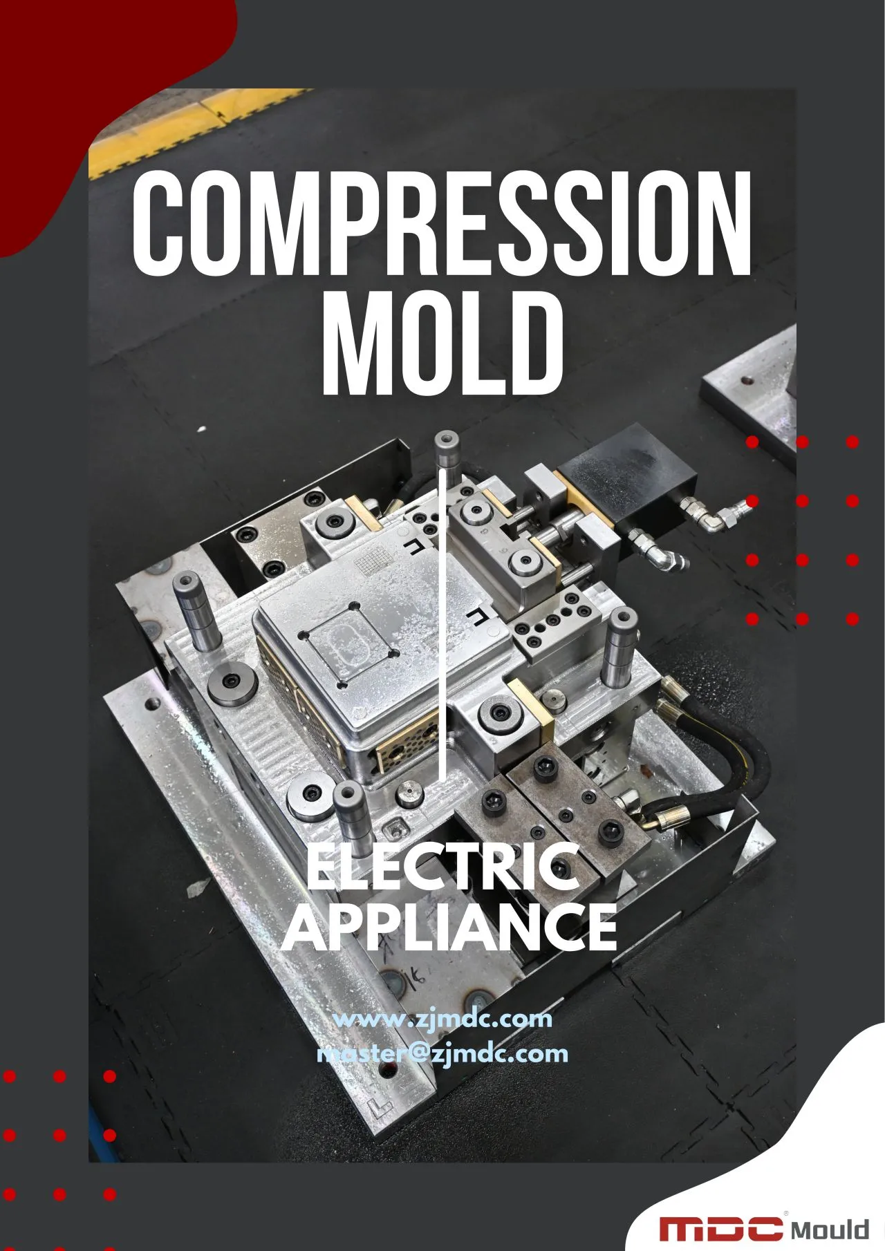
compression mould company

Why Choose MDC for Composite Tooling?

MDC manufactures customized composite molds and composite tooling for different composite manufacturing applications. Our engineering approach combines mould design, precision machining, surface finishing, assembly, inspection, and tooling validation.

Rather than applying the same mould structure to every project, MDC considers the product geometry, composite material, molding process, production volume, equipment, and required product quality when developing the tooling.

Engineering-Based Mold Development

Product geometry and manufacturing requirements are reviewed before mould construction begins. This helps identify potential issues related to draft, parting lines, material flow, demoulding, and tooling structure.

Precision Machining

CNC machining and precision finishing are used to produce cavity and core surfaces according to the approved tooling design.

Composite Tooling Experience

MDC’s tooling experience covers applications involving SMC, BMC, carbon fiber, FRP, and other composite materials and forming processes.

Production-Oriented Approach

The final objective is not simply to manufacture an accurate mould. The tooling should support stable production, consistent part quality, efficient demoulding, and practical maintenance throughout its service life.

Frequently Asked Questions About Composite Molds

What is a composite mold?

A composite mold is a precision tooling system used to form or cure composite materials into a specific product geometry. It can be designed for materials and processes including carbon fiber, SMC, BMC, FRP, prepreg, compression molding, and other composite manufacturing methods.

What is the difference between a composite mold and a composite tool?

The terms are often used interchangeably in composite manufacturing. In general, composite tooling can refer to the broader tooling system used for composite production, while a composite mold specifically refers to the forming tool or mould surface that defines the component geometry.

What materials can be processed using composite molds?

The suitable material depends on the tooling design and manufacturing process. Composite molds may be designed for carbon fiber composites, SMC, BMC, FRP, prepreg, and other reinforced polymer systems.

Why is surface finish important for composite tooling?

The mould cavity can directly influence the surface appearance of the finished composite part. Accurate machining and appropriate polishing help reproduce the required surface characteristics consistently.

Why is temperature control important in composite molding?

Temperature can influence material flow, curing, dimensional stability, and cycle consistency. A suitable heating configuration helps establish more stable thermal conditions throughout the mould.

Can one composite mold be used for different materials?

It depends on the material systems and molding processes involved. Tooling temperature, pressure, chemical compatibility, surface requirements, and curing conditions should be evaluated before using a mould for a different material.

Can MDC manufacture customized composite molds?

Yes. MDC manufactures customized composite molds according to product geometry, material, molding process, production volume, equipment, surface requirements, and customer specifications.

Does MDC manufacture carbon fiber molds?

Yes. MDC manufactures customized tooling for carbon fiber and other composite applications, with mould design adapted to the selected material and production process.

Does MDC manufacture SMC and BMC molds?

Yes. MDC manufactures customized SMC and BMC compression moulds for automotive, electrical, sanitaryware, industrial, and other composite applications.

Conclusion

A high-performance composite mold is more than a precisely machined cavity. It is an engineered tooling system in which dimensional accuracy, mould rigidity, surface finish, thermal stability, venting, parting-line control, and demoulding performance work together.

Because composite materials and molding processes vary significantly, the tooling should be developed according to the actual application rather than using a universal mould structure.

At MDC, we manufacture composite molds, composite moulds, compression moulds, carbon fiber tooling, SMC moulds, BMC moulds, and customized composite tooling for a wide range of industrial applications.

From product analysis and DFM to mould design, CNC machining, surface finishing, assembly, inspection, and trial molding, MDC focuses on producing tooling that supports reliable and repeatable composite manufacturing.

Contact MDC for a customized composite mold solution based on your product, material, molding process, and production requirements.

Precision SMC Composite Bathtub Mould Solutions

Precision SMC composite bathtub moulds manufactured by MDC Mould. Features SPI A1 mirror polish, optimized deep-draw draft angles, and multi-zone heating.

A bathtub mould is not simply a tool for creating the required shape. Large composite bathtub components have relatively large forming surfaces and often require strict control of dimensional accuracy, surface finish, wall geometry, and demoulding performance.

For composite and SMC bathtubs, the mould surface is directly transferred to the finished product. Accurate cavity machining, appropriate draft angles, reliable mould structure, effective venting, and controlled thermal conditions all contribute to stable production and repeatable product quality.

At MDC, we manufacture customized bathtub moulds and composite tooling for sanitaryware applications. Our mould solutions are developed around practical production requirements, including product geometry, material behavior, surface appearance, production volume, and demoulding conditions.

What Makes a Bathtub Mould Different from General Composite Tooling?

Bathtub moulds have several characteristics that make their design different from smaller composite tooling applications. A bathtub typically has a relatively large cavity, broad curved surfaces, deep forming areas, and visible cosmetic surfaces. These characteristics increase the importance of mould rigidity, machining accuracy, surface finishing, and thermal consistency.

A large composite bathtub mould must maintain its geometry while handling repeated molding cycles. Even relatively small dimensional deviations across a large cavity can become noticeable in the finished bathtub.

Important tooling considerations include:

  • Large-area cavity accuracy
  • Stable mould structure
  • Consistent surface finish
  • Controlled draft angles
  • Reliable demoulding
  • Effective venting
  • Uniform thermal distribution
  • Long-term dimensional stability

The objective is not simply to manufacture a mould that produces one acceptable part, but to create tooling capable of maintaining consistent quality throughout repeated production cycles.

Surface Finish Is Critical for Composite Bathtub Moulds

The cavity surface of a bathtub mould has a direct influence on the appearance of the finished bathtub. Unlike hidden structural components, bathtubs are highly visible products where surface quality is an important part of the customer’s perception of the final product.

A properly finished cavity can help reproduce a smooth and consistent surface while reducing unnecessary post-processing on the molded bathtub.

Precision Machining Before Polishing

Surface quality starts with accurate machining. CNC machining establishes the basic cavity geometry and determines how consistently the final surface can be finished.

Machining errors, excessive tool marks, local steps, or uneven transitions can make subsequent polishing more difficult and may become visible on the finished product.

Polishing of the Mould Cavity

After machining, critical cavity surfaces may require grinding and polishing according to the required bathtub appearance. The final surface condition should be selected based on the product’s cosmetic requirements and manufacturing process.

A well-prepared mould surface can provide several production benefits:

  • Improved bathtub surface appearance
  • More consistent gloss and texture
  • Reduced material adhesion
  • Easier demoulding
  • Lower secondary finishing requirements
  • More consistent production results
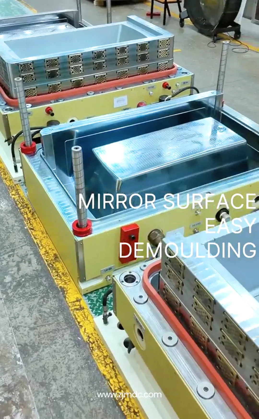
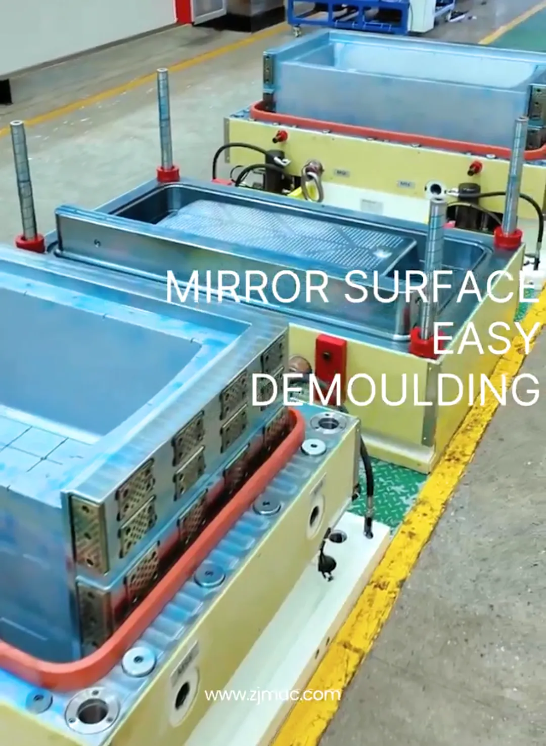
bathtub mould2

Dimensional Accuracy in Bathtub Mould Manufacturing

Dimensional accuracy is particularly important for large bathtub moulds because the finished product must maintain the intended overall geometry while also fitting associated components such as frames, supports, drains, panels, seals, or installation structures.

An accurately manufactured bathtub mould provides a stable reference for the finished composite component. Critical dimensions should therefore be identified during the mould design stage and controlled throughout machining and inspection.

Large Cavity Geometry

Large cavity surfaces require careful machining and inspection because small deviations can accumulate across the forming area. The mould structure must also provide sufficient rigidity to minimize deformation during manufacturing and operation.

Shrinkage Compensation

Composite materials can experience dimensional changes during curing and cooling. The mould design should take the expected material behavior into consideration so that the finished bathtub can achieve the required dimensions.

The exact compensation strategy depends on the material system, molding process, product geometry, and processing conditions.

Critical Assembly Dimensions

Where the bathtub interfaces with drains, support structures, covers, panels, or other components, the corresponding mould features require additional attention.

Maintaining these critical dimensions helps improve assembly consistency and reduces the need for corrective operations during final production.

Draft Angle and Demoulding Design for Bathtub Moulds

Because a bathtub has a relatively deep and curved cavity, demoulding must be considered from the beginning of the tooling design process. A mould that produces the correct geometry but cannot release the part reliably is not an efficient production mould.

Draft angles provide clearance between the molded part and the mould surface during separation. The required draft depends on the bathtub geometry, surface finish, material characteristics, and production process.

Insufficient draft may increase demoulding force and create risks such as:

  • Surface scratching
  • Part deformation
  • Edge damage
  • Cracking around local features
  • Longer production cycles
  • Increased mould wear

For complex bathtub geometries, engineers must consider deep sections, sharp transitions, local ribs, mounting features, and areas where the product may mechanically lock against the cavity.

Mould Rigidity for Large Bathtub Tooling

The size of a bathtub makes mould rigidity an important engineering consideration. Large tooling surfaces can be affected by mechanical loads, thermal expansion, handling, and repeated production cycles.

A rigid bathtub compression mould helps maintain the designed cavity geometry and reduces the risk of deformation during molding.

The supporting structure should be designed according to:

  • Overall bathtub dimensions
  • Cavity depth
  • Molding pressure
  • Mould weight
  • Heating requirements
  • Expected production volume
  • Press or production equipment

Adequate structural support is particularly important when the tooling is used repeatedly in medium- or high-volume production.

Temperature Control for Large Composite Bathtub Moulds

Temperature control becomes increasingly important as the size of the bathtub mould increases. A large cavity requires a stable thermal environment so that the composite material can flow and cure consistently across the entire forming surface.

An improperly balanced heating system may create temperature differences between different areas of the mould. These differences can influence curing behavior, material flow, surface quality, and dimensional stability.

For a bathtub compression mould, the heating system should therefore be considered together with the mould structure and cavity geometry rather than treated as an independent component.

Uniform Thermal Distribution

Large flat or curved areas may require carefully positioned heating elements or heating channels to minimize temperature differences across the cavity. The objective is to provide stable and repeatable thermal conditions throughout the production cycle.

Uniform temperature distribution can help reduce:

  • Uneven curing
  • Dimensional variation
  • Surface quality differences
  • Residual stress
  • Local warpage
  • Production cycle variation

Thermal Stability During Repeated Production

A bathtub mould used for continuous production experiences repeated heating and cooling cycles. The tooling structure and heating system should therefore be designed with long-term thermal stability in mind.

Consistent thermal performance helps manufacturers maintain more predictable production conditions and reduces the need for frequent process adjustments.

Venting Design for Composite Bathtub Moulds

Effective venting is another important consideration when designing a composite bathtub mould. During molding, air and gases inside the cavity need to escape as the material fills the mould.

If air becomes trapped in difficult-to-fill areas, the finished bathtub may develop surface imperfections, voids, incomplete filling, or localized defects.

Venting locations should be selected according to:

  • Cavity geometry
  • Material flow direction
  • Parting-line configuration
  • Deep or enclosed areas
  • Potential air-trapping locations
  • Expected molding conditions

The objective is to provide sufficient air-release paths while controlling material leakage through the venting system.

For large bathtub components, venting should be evaluated during the mould design stage rather than added only after production problems occur.

Flash Control in Bathtub Compression Moulding

Flash is a common concern in compression molding because excess material can escape through the mould parting surface when the cavity is compressed.

For large sanitaryware components, excessive flash increases trimming requirements and may affect the appearance or dimensional accuracy of the finished bathtub.

Flash formation can be influenced by several factors, including:

  • Parting-line accuracy
  • Mould closing condition
  • Material charge
  • Molding pressure
  • Mould wear
  • Cavity design
  • Material flow behavior

A precision bathtub mould should therefore incorporate carefully designed parting surfaces and sufficient structural rigidity to maintain stable mould closure during production.

Reducing flash at the tooling stage can also reduce downstream trimming work and improve overall manufacturing efficiency.

Common Bathtub Moulding Problems and Engineering Solutions

Large composite bathtub components can experience different types of molding defects depending on the material, tooling, equipment, and processing conditions. Understanding the relationship between a defect and its potential cause helps engineers determine the most appropriate corrective action.

Common ProblemPossible CauseEngineering Consideration
Surface ImperfectionsPoor cavity finish, trapped air, contamination, or unstable molding conditionsImprove mould finishing, venting, cleaning, and process stability
Excessive FlashParting-line clearance, mould wear, excessive material, or pressureImprove parting surfaces and review material loading and molding parameters
WarpageUneven curing, thermal imbalance, wall thickness variation, or residual stressOptimize mould temperature distribution and review product geometry
Dimensional VariationMould deformation, material shrinkage, or unstable thermal conditionsImprove mould rigidity, dimensional compensation, and thermal control
Difficult DemouldingInsufficient draft, surface adhesion, or unsuitable cavity finishReview draft angles, surface condition, and release strategy
Incomplete FillingIncorrect material loading, restricted flow, or unsuitable process conditionsReview charge placement, cavity design, material flow, and molding parameters
Local Surface VariationUneven material distribution or temperature differencesOptimize material flow and thermal balance

It is important to understand that not every molding defect originates from the mould itself. Material properties, charge weight, loading position, molding temperature, pressure, curing time, and press performance can also influence the final result.

A complete engineering evaluation should therefore consider the mould and molding process as an integrated production system.

Trial Moulding for Bathtub Tooling Validation

Trial moulding provides an important opportunity to verify whether a newly manufactured bathtub mould can achieve the required production performance.

Rather than evaluating only whether the mould can produce the correct basic shape, trial production allows engineers to examine the interaction between tooling, material, molding equipment, and process parameters.

Checking Bathtub Geometry

The trial part can be inspected to verify overall dimensions, critical interfaces, cavity features, wall geometry, and other customer-defined requirements.

Evaluating Surface Quality

The molded surface is examined for defects such as uneven appearance, pits, pinholes, resin-rich areas, fiber exposure, or other abnormalities that may require tooling or process adjustments.

Evaluating Demoulding

The release process is observed carefully to determine whether the bathtub separates smoothly from the mould without excessive force or damage.

Checking Flash and Parting-Line Performance

Trial production also provides an opportunity to evaluate flash distribution and the performance of the mould parting surfaces under actual production conditions.

The information obtained during trial moulding can then be used to optimize the tooling before regular production begins.

Quality Inspection for Bathtub Mould Manufacturing

Quality control is an important part of manufacturing large composite tooling. Because bathtub moulds contain large curved surfaces and complex geometry, inspection should cover both dimensional accuracy and functional tooling performance.

Inspection StageKey Inspection Items
Raw Material InspectionSteel grade, material certification, and condition
CNC Machining InspectionCavity dimensions, geometry, and critical tolerances
Surface Finishing InspectionPolishing quality, machining marks, and cavity condition
Assembly InspectionAlignment, fitting, parting surfaces, and mould structure
Heating System InspectionHeating configuration and thermal performance
Trial MouldingProduct dimensions, surface quality, flash, and demoulding
Final InspectionCompliance with approved drawings and customer specifications

A structured inspection process helps identify tooling issues before they become repeated production problems and provides greater confidence in the long-term performance of the mould.

From Bathtub Product Design to Production-Ready Tooling

Successful bathtub tooling begins before machining starts. Product geometry, material selection, molding process, production volume, and available equipment should all be considered during the engineering stage.

At MDC, the development process can include:

  1. Product Drawing and 3D Model Review – Analyze the bathtub geometry, dimensions, tolerances, and functional areas.
  2. DFM Analysis – Review draft angles, parting lines, wall geometry, demoulding conditions, and potential material-flow issues.
  3. Mould Structure Design – Develop the cavity, core, support structure, heating system, venting, and other required tooling features.
  4. Precision CNC Machining – Manufacture the mould components according to approved engineering specifications.
  5. Grinding and Polishing – Finish the cavity surface according to the required bathtub appearance.
  6. Mould Assembly – Assemble the mould components and verify fitting and alignment.
  7. Dimensional Inspection – Check critical mould dimensions and functional areas.
  8. Trial Moulding – Validate the mould under practical production conditions.
  9. Tool Optimization – Make necessary adjustments based on trial results.
  10. Final Approval – Complete final inspection before production release.

This engineering workflow helps transform the bathtub mould from a machined tool into a production-ready tooling system capable of supporting consistent composite manufacturing.

MDC Bathtub Mould Manufacturing Capability

At MDC, we manufacture customized bathtub moulds for composite and SMC sanitaryware applications. Our tooling solutions are developed according to the product structure, material system, molding process, production volume, and required surface quality.

For large bathtub tooling, our engineering approach focuses on maintaining cavity accuracy and structural stability while providing the surface finish and demoulding performance required for practical production.

Precision Cavity Manufacturing

The cavity geometry is manufactured using precision machining processes to reproduce the required bathtub shape accurately. Particular attention is given to large curved surfaces, transition areas, edges, and critical functional features.

Composite Tooling Experience

MDC has experience in manufacturing tooling for composite applications, including compression moulds and other customized composite mould solutions. This experience allows the tooling design to consider material behavior and actual molding conditions rather than focusing only on the product geometry.

Surface Finishing

For visible bathtub surfaces, mould finishing is an important part of the tooling process. Grinding and polishing are performed according to the required product appearance and production requirements.

Production-Oriented Engineering

MDC develops moulds with production conditions in mind. Mould rigidity, heating, venting, parting surfaces, draft angles, and demoulding are considered during tooling development to support repeatable manufacturing.

Trial and Tool Optimization

Where required, trial moulding can be used to verify product dimensions, surface quality, flash, filling behavior, and demoulding performance. The results provide practical information for final tooling optimization.

Composite and SMC Bathtub Applications

Different bathtub manufacturers may use different composite material systems and production processes. The tooling design should therefore be developed according to the specific material and manufacturing method rather than assuming that every bathtub mould can use the same configuration.

SMC Bathtubs

SMC bathtub moulds are designed for compression molding applications where the material is formed and cured under controlled heat and pressure. Tooling must accommodate material flow, curing behavior, flash control, and reliable demoulding.

FRP and Composite Bathtubs

FRP and other composite bathtub manufacturing processes may require different tooling configurations depending on the forming and curing method. Surface quality, release performance, dimensional stability, and mould durability remain important considerations.

Customized Sanitaryware Products

Beyond standard bathtub designs, composite tooling can also be developed for customized sanitaryware products with special dimensions, contours, mounting areas, or surface requirements.

The mould structure should be adapted to the actual product rather than relying on a standardized tooling design.

What Information Should You Provide for a Bathtub Mould Project?

Providing complete technical information allows the tooling engineer to evaluate the project more accurately and develop a mould that matches the intended production process.

For a bathtub mould project, customers should ideally provide:

  • 3D product model or 2D engineering drawing
  • Overall bathtub dimensions
  • Material specification
  • Molding or forming process
  • Expected production volume
  • Required surface finish
  • Critical dimensional tolerances
  • Available molding equipment
  • Demoulding requirements
  • Special inserts or functional features
  • Inspection and acceptance requirements

If the production process or material specification is still under development, the tooling design can be evaluated based on the available product information and expected manufacturing conditions.

How to Select a Bathtub Mould Manufacturer

When selecting a bathtub mould manufacturer, buyers should evaluate more than machining capability. Large composite tooling requires an understanding of product geometry, material behavior, mould structure, surface finishing, and production conditions.

Important factors to consider include:

  • Experience with large composite moulds
  • SMC and compression moulding knowledge
  • Precision CNC machining capability
  • Large cavity surface finishing capability
  • Mould structural design experience
  • Heating and thermal management knowledge
  • Venting and flash-control design
  • Trial moulding capability
  • Dimensional inspection and quality control
  • Technical communication and project support

A reliable tooling partner should be able to explain how each mould design decision supports the customer’s actual production requirements, rather than simply providing a mould based on a drawing.

bathtub mould

Frequently Asked Questions About Bathtub Moulds

What is a bathtub mould?

A bathtub mould is a tooling system used to form a bathtub component from materials such as SMC, FRP, or other composite materials. The mould defines the product geometry and strongly influences dimensional accuracy, surface finish, and demoulding performance.

What is an SMC bathtub mould?

An SMC bathtub mould is a compression mould specifically designed for forming SMC material into a bathtub or related sanitaryware component. Its design must consider material flow, curing, temperature control, flash, surface finish, and demoulding.

Why is surface finish important for a bathtub mould?

The mould cavity transfers its surface characteristics to the finished bathtub. A properly machined and polished cavity can help achieve a consistent appearance and reduce surface-related finishing work.

Why are draft angles important in bathtub mould design?

Draft angles provide clearance between the mould and the molded bathtub during demoulding. Proper draft design helps reduce release resistance and lowers the risk of scratching, deformation, or damage to the finished component.

How does mould rigidity affect bathtub production?

Mould rigidity helps maintain cavity geometry under mechanical and thermal loads. Stable tooling supports dimensional consistency and reduces the risk of deformation during repeated production cycles.

How can flash be reduced in bathtub compression moulding?

Flash can be influenced by parting-line accuracy, mould wear, material charge, molding pressure, and cavity design. Accurate parting surfaces combined with appropriate material and process control can help reduce excessive flash.

What materials can be used with bathtub moulds?

The suitable material depends on the bathtub manufacturing process. Composite bathtub applications may use SMC, FRP, or other composite systems, and the mould should be designed according to the specific material and curing or forming conditions.

Can MDC manufacture customized bathtub moulds?

Yes. MDC manufactures customized bathtub moulds according to product geometry, material, molding process, production volume, surface requirements, equipment conditions, and customer specifications.

Does MDC manufacture SMC compression moulds?

Yes. MDC manufactures customized compression moulds for SMC applications, including sanitaryware and other composite components requiring accurate cavity geometry and repeatable production performance.

Can bathtub moulds be used for high-volume production?

Yes. A properly engineered bathtub mould can be designed for repeated production cycles. Tool material, mould rigidity, thermal management, surface finishing, maintenance, and production conditions should all be considered when determining the appropriate tooling configuration.

Conclusion: Precision Tooling for Consistent Bathtub Production

A successful bathtub mould does more than reproduce the basic shape of a sanitaryware product. For large composite components, cavity accuracy, surface finish, mould rigidity, draft angles, venting, thermal stability, and demoulding performance all contribute to the final production result.

The larger the forming surface, the more important it becomes to control these factors as an integrated tooling system. Accurate machining establishes the geometry, surface finishing determines the quality of the visible cavity, thermal management supports consistent processing, and proper draft and demoulding design helps protect the finished bathtub.

At MDC, we manufacture bathtub moulds, SMC bathtub moulds, compression moulds, and customized composite tooling for sanitaryware applications. From product and DFM review to CNC machining, polishing, assembly, inspection, and trial moulding, our tooling development process is focused on practical production requirements and repeatable results.

Whether you are developing a standard composite bathtub, an SMC sanitaryware product, or a customized large-format composite component, MDC can develop a mould solution based on your product geometry, material system, production process, and quality requirements.

Contact MDC to discuss your bathtub mould and composite tooling project.

SMC Compression Moulds for Meter & Electrical Box Covers

Custom SMC compression moulds for electrical enclosure covers by MDC Mould. Engineered for UL 94-V0 flame retardancy, IP65+ sealing, and high dielectric strength.

Electrical enclosure covers require more than dimensional accuracy. They must provide stable mechanical performance, consistent wall thickness, reliable electrical insulation, and a high-quality surface finish to ensure dependable assembly and long-term service.

Compression moulding is well suited for manufacturing SMC electrical components because it can produce complex composite geometries with consistent dimensions, excellent surface quality, and repeatable production performance. For medium- and high-volume manufacturing, a properly engineered SMC mould can help maintain stable product quality while reducing production variation.

At MDC, we manufacture customized compression moulds for electrical enclosure covers and other SMC electrical components. Our tooling solutions are developed according to product geometry, material characteristics, press conditions, production volume, and customer quality requirements.

Why SMC Compression Moulding Is Suitable for Electrical Enclosure Covers

Electrical enclosure covers are often required to combine mechanical strength, dimensional stability, electrical insulation, heat resistance, and long-term environmental durability. These requirements make fiber-reinforced thermoset composites such as SMC suitable for many electrical enclosure applications.

Compared with conventional materials, SMC can provide a combination of structural and electrical properties while supporting efficient compression moulding production. The material can also be molded into complex shapes with ribs, mounting features, bosses, openings, and other integrated details.

A well-designed SMC compression mould helps manufacturers achieve:

  • Stable product dimensions
  • Consistent wall thickness
  • Good surface quality
  • Reliable electrical insulation
  • Repeatable production performance
  • Reduced secondary machining
  • Efficient medium- and high-volume manufacturing

However, these advantages depend heavily on the quality of the mould and the control of the compression moulding process. Mould geometry, material flow, temperature distribution, venting, and demoulding all influence the final electrical enclosure cover.

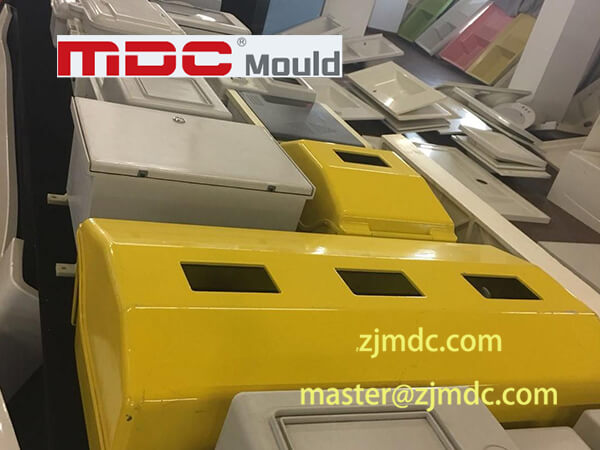
mould electrical covers

Key Mould Design Requirements for Electrical Covers

An electrical enclosure cover may appear relatively simple from the outside, but its internal structure can contain multiple functional features. Mounting holes, ribs, sealing areas, screw bosses, reinforcing sections, and interfaces with the enclosure body must all be accurately reproduced by the mould.

For this reason, the design of an electrical enclosure mould should consider both product geometry and the behavior of SMC during compression moulding.

Dimensional Accuracy

Dimensional accuracy is critical because electrical enclosure covers must normally fit with a corresponding base, frame, gasket, fastening system, or electrical assembly. Excessive dimensional variation can create assembly difficulties or compromise sealing performance.

The mould cavity and core must therefore be manufactured according to carefully controlled engineering tolerances. Shrinkage compensation should also be considered during the tooling design stage to ensure that the finished SMC component achieves the required dimensions.

Consistent Wall Thickness

Wall thickness has a direct influence on the mechanical and dimensional performance of an electrical enclosure cover. Significant thickness variation may affect material flow, curing behavior, shrinkage, and local strength.

A properly engineered mould helps distribute SMC material consistently throughout the cavity while maintaining the intended wall structure. This is particularly important for covers containing ribs, corners, bosses, and reinforced sections.

Parting Line Design

The parting line is another important consideration when designing a compression mould for electrical covers. Its position influences flash formation, dimensional accuracy, mould maintenance, and the appearance of the finished component.

An optimized parting line should provide reliable mould closure while minimizing excessive flash and avoiding interference with important sealing or assembly surfaces.

SMC Material Flow in Electrical Enclosure Cover Moulding

During compression moulding, SMC material is placed into the mould and compressed under controlled pressure and temperature. As the mould closes, the material flows through the cavity before curing into the final composite structure.

The flow behavior of SMC must be considered carefully when designing an SMC mould for electrical covers. Complex geometry, long flow distances, narrow sections, ribs, and changes in wall thickness can all affect material distribution.

Poor material flow may result in:

  • Incomplete cavity filling
  • Uneven wall thickness
  • Fiber distribution variation
  • Resin-rich areas
  • Surface defects
  • Local weakness
  • Excessive flash

Mould engineers therefore evaluate the product geometry and material loading strategy before finalizing the tooling design. The objective is to achieve predictable material flow and sufficient cavity filling without creating unnecessary pressure concentrations or excessive material movement.

Venting Design for SMC Electrical Enclosure Moulds

Venting is an important part of compression mould design for electrical components. During mould closing and curing, air and gases must be released from the cavity. If they become trapped, surface defects, voids, incomplete filling, or localized quality problems may occur.

Properly positioned vents provide controlled pathways for air and gases to escape while minimizing unwanted SMC leakage.

For electrical enclosure covers, effective venting contributes to:

  • Better surface appearance
  • More complete cavity filling
  • Reduced air entrapment
  • Lower risk of surface porosity
  • More consistent molded dimensions
  • Improved production stability

The venting strategy should be developed according to cavity geometry, material flow direction, parting line configuration, and expected production conditions rather than relying on a standard vent arrangement.

design

Temperature Control in Compression Moulding for Electrical Covers

Temperature control is one of the most important factors in producing consistent SMC electrical enclosure covers. Because SMC is a thermosetting composite material, the molding temperature directly affects resin flow, curing behavior, dimensional stability, surface quality, and cycle time.

An SMC compression mould should therefore be designed with a heating system that provides stable and reasonably uniform temperature distribution across the cavity and core. Uneven heating can cause different areas of the component to cure at different rates, increasing the risk of warpage, dimensional variation, or surface defects.

Uniform Heating Across the Mould

Large electrical enclosure covers often have relatively broad molding surfaces. If the temperature distribution is not properly balanced, different regions of the part may experience different curing conditions.

MDC considers the mould structure, cavity geometry, heating arrangement, and expected production cycle when developing the thermal system. The objective is to provide stable heating conditions throughout the molding area and maintain repeatable production performance.

Temperature Stability and Product Consistency

Stable mould temperature helps maintain predictable SMC flow and curing behavior. This contributes to consistent dimensions, surface appearance, and mechanical properties from one production cycle to the next.

For production environments where electrical enclosure covers are manufactured continuously, thermal stability is particularly important because small process variations can accumulate into higher rejection rates over time.

Surface Finish Requirements for Electrical Enclosure Covers

The mould surface directly influences the appearance of the finished SMC electrical cover. Electrical enclosure products may require smooth, uniform surfaces because they are often visible components or must interface with gaskets, labels, mounting hardware, and other assemblies.

A high-quality electrical enclosure mould should therefore provide a cavity surface appropriate for the customer’s final product requirements.

Depending on the application, surface finishing may include:

  • Precision machining
  • Fine grinding
  • Polishing
  • Texture finishing
  • Localized surface treatment

Proper surface finishing can improve the visual consistency of molded parts while also supporting reliable demoulding. It can reduce material adhesion and make mould maintenance easier during long production runs.

Surface Quality and Electrical Enclosure Assembly

Surface quality is not only an aesthetic consideration. Certain areas of an electrical cover may need to provide accurate contact with seals, fasteners, frames, or mating components. Excessive surface irregularities can therefore affect assembly performance.

For this reason, critical sealing and assembly surfaces should be identified during the mould design stage rather than treated only as a finishing issue after machining.

Demoulding Design for SMC Electrical Covers

Reliable demoulding is essential for maintaining production efficiency. After curing, the SMC component must be removed from the mould without damaging edges, ribs, mounting features, or visible surfaces.

An improperly designed mould may create excessive demoulding resistance. This can lead to scratches, deformation, broken features, or production downtime.

Draft Angles

Appropriate draft angles help the molded electrical cover separate from the cavity and core smoothly. The required angle depends on part geometry, surface finish, texture, material characteristics, and customer requirements.

Ejection and Release Considerations

Where the product structure requires additional assistance during demoulding, the mould design can incorporate suitable ejection or release features. These features must be positioned carefully to avoid damaging functional or cosmetic areas of the component.

Good demoulding design helps reduce:

  • Part damage
  • Production cycle interruptions
  • Manual removal effort
  • Mould surface wear
  • Unnecessary maintenance

Mould Rigidity and Long-Term Dimensional Stability

Electrical enclosure covers are often produced in repeated molding cycles, which means the tooling must maintain its geometry under continuous mechanical and thermal loading.

A rigid compression mould minimizes deformation during press operation and helps maintain consistent cavity dimensions over long production periods. This is particularly important for larger enclosure covers where mould size and forming area increase the potential for deflection.

Mould structure should therefore be designed according to:

  • Part size and geometry
  • Required molding pressure
  • Press specifications
  • Mould steel selection
  • Heating system arrangement
  • Expected production volume

Adequate structural rigidity supports dimensional repeatability and helps reduce tooling deformation during production.

Material Selection for Electrical Enclosure Cover Moulds

Tool steel selection affects machining performance, wear resistance, thermal stability, surface finishing, and mould service life. The appropriate material should be selected according to production requirements rather than using the same specification for every application.

Mould MaterialTypical CharacteristicsPotential Application
P20 SteelGood machinability and cost efficiencyPrototype and moderate-volume tooling
718 SteelGood strength, machinability, and polishing performanceGeneral industrial and electrical composite tooling
H13 SteelGood thermal fatigue resistance and durabilityHigh-cycle compression moulding applications

The final material specification should also consider heat treatment, mould operating temperature, production cycle, expected tool life, and maintenance requirements.

How Mould Design Affects Electrical Cover Quality

Mould Design FactorPotential Effect on Electrical Cover
Cavity AccuracyControls dimensional consistency and assembly fit
Wall Thickness DesignInfluences material flow, strength, and shrinkage
Parting LineAffects flash, appearance, and sealing areas
VentingHelps reduce trapped air and surface defects
Heating SystemInfluences curing consistency and dimensional stability
Surface FinishAffects appearance and demoulding performance
Mould RigiditySupports long-term dimensional stability
Draft DesignImproves demoulding and reduces part damage

The important point is that these factors do not work independently. A reliable electrical enclosure cover mould requires the cavity, thermal system, venting structure, parting line, surface finish, and mechanical structure to work together as one tooling system.

Quality Control for Electrical Enclosure Compression Moulds

The quality of an SMC mould directly affects the consistency of the electrical enclosure covers produced from it. For this reason, tooling quality should be controlled throughout the entire manufacturing process rather than relying only on a final visual inspection.

A professional compression mould manufacturer evaluates critical dimensions, cavity geometry, parting surfaces, heating systems, venting features, surface finish, and assembly accuracy before the mould enters production.

Dimensional Inspection

Critical mould dimensions are checked against approved product drawings and tooling specifications. Particular attention is given to cavity dimensions, mounting features, sealing surfaces, inserts, and parting-line areas.

Accurate dimensional inspection helps ensure that the finished SMC electrical cover meets the required assembly and functional tolerances.

Cavity and Parting Surface Inspection

The cavity surface and parting line are inspected to identify machining marks, local deformation, excessive gaps, or other conditions that could influence product quality.

A precise parting surface is especially important for controlling flash. Excessive clearance between the mould halves can allow SMC material to escape during compression and create additional trimming work.

Heating System Verification

The mould heating system should be checked before production to confirm that the designed heating configuration can provide stable thermal conditions.

Temperature verification helps identify potential hot spots or cold areas that could result in inconsistent curing or dimensional variation in the electrical enclosure cover.

Trial Moulding

Trial moulding is an essential stage in the development of an electrical enclosure cover mould. It provides an opportunity to evaluate the actual interaction between the mould, SMC material, molding press, and processing parameters.

During trial production, engineers may evaluate:

  • Material filling behavior
  • Flash distribution
  • Surface appearance
  • Wall thickness consistency
  • Part dimensions
  • Demoulding performance
  • Curing condition
  • Mould temperature stability

The trial results can then be used to make controlled tooling or process adjustments before mass production begins.

Common SMC Electrical Cover Moulding Defects and Solutions

Even when the basic mould design is correct, production defects may occur if tooling conditions, material loading, temperature, pressure, or curing parameters are not properly controlled. Understanding the relationship between the defect and its potential cause helps engineers solve problems more efficiently.

DefectPossible CausePotential Solution
Excessive FlashParting-line clearance, excessive molding pressure, or mould wearImprove parting surface accuracy, review pressure settings, and maintain sealing surfaces
Incomplete FillingInsufficient material, unsuitable loading position, low temperature, or restricted flowOptimize material charge, loading position, temperature, and cavity design
WarpageUneven curing, temperature imbalance, non-uniform wall thickness, or residual stressImprove thermal balance and review product and mould geometry
Surface DefectsPoor mould finish, trapped air, contamination, or unstable processing conditionsImprove cavity finishing, venting, cleaning, and process control
Dimensional VariationMould deformation, inconsistent temperature, or material shrinkage variationImprove mould rigidity, thermal control, and shrinkage compensation
Fiber ExposureMaterial flow conditions, insufficient resin coverage, or process instabilityReview material loading and molding parameters and verify mould surface condition
Difficult DemouldingInsufficient draft, surface adhesion, or unsuitable cavity finishReview draft angles, surface finish, and release conditions

The key principle is that a molding defect should not automatically be attributed to the mould alone. Product geometry, SMC material condition, molding temperature, pressure, curing time, loading strategy, and press performance can all influence the final result.

A systematic engineering approach helps distinguish tooling-related problems from process-related problems and leads to more effective corrective action.

Trial Moulding and Tool Optimization for Electrical Covers

For complex electrical enclosure covers, the first mould trial is not simply a pass-or-fail inspection. It provides valuable production data that can be used to optimize the complete tooling and molding system.

Evaluating Material Distribution

Engineers examine the molded component to determine whether SMC material has distributed evenly throughout the cavity. Areas around ribs, corners, bosses, and deep features require particular attention because changes in geometry can influence material flow.

Checking Product Dimensions

Critical dimensions are measured after trial molding to determine whether the mould correctly compensates for expected material shrinkage and thermal effects.

Where necessary, tooling adjustments can be made before the mould is released for production.

Evaluating Surface Quality

The molded surface is inspected for gloss variation, pits, pinholes, fiber exposure, resin-rich areas, and other visible defects. These observations help determine whether additional mould finishing, venting adjustments, or process optimization is required.

Confirming Demoulding Performance

The component should separate from the mould without excessive force or damage. If sticking or deformation occurs, engineers can review draft angles, cavity surface condition, release strategy, and local product geometry.

This trial-and-optimization approach helps transform a newly manufactured mould into a production-ready tooling system rather than treating mould delivery as the end of the engineering process.

MDC Manufacturing Process for Electrical Enclosure Moulds

At MDC, the development of an SMC compression mould follows a structured manufacturing process designed around the customer’s product requirements and production conditions.

  1. Product and Drawing Review: Analyze product geometry, tolerances, material specifications, and functional requirements.
  2. DFM Analysis: Review wall thickness, ribs, bosses, draft angles, parting lines, material flow, and demoulding conditions.
  3. 3D Mould Design: Develop the cavity, core, inserts, heating system, venting system, and supporting structure.
  4. Material Preparation: Select and prepare suitable mould steel according to production requirements.
  5. CNC Machining: Manufacture mould components and cavity surfaces according to engineering specifications.
  6. Heat Treatment: Apply appropriate heat treatment where required to improve hardness, wear resistance, and dimensional stability.
  7. Precision Finishing: Perform grinding, fitting, polishing, and other finishing operations.
  8. Mould Assembly: Assemble cores, cavities, inserts, heating components, and other tooling elements.
  9. Inspection: Verify critical dimensions, alignment, parting surfaces, and mould functionality.
  10. Trial Moulding: Test the tooling under practical molding conditions and evaluate the resulting electrical cover.
  11. Tool Optimization: Make necessary adjustments based on trial results and customer requirements.
  12. Final Approval: Complete final inspection before the tooling is prepared for production.

This process allows MDC to consider the mould as part of the complete manufacturing system. The goal is not simply to produce a precisely machined tool, but to deliver tooling that can support stable and repeatable production of SMC electrical enclosure covers.

Applications of Compression Moulds for Electrical Enclosure Covers

SMC electrical enclosure covers are used in applications where electrical insulation, mechanical strength, dimensional stability, and environmental resistance are important. The combination of composite material performance and compression moulding efficiency makes SMC suitable for a wide range of electrical and industrial products.

Electrical Distribution Equipment

SMC enclosure covers can be used for electrical distribution equipment and protective housings where reliable insulation and dimensional stability are required. Precision tooling helps maintain consistent interfaces between covers, internal components, and enclosure bases.

Switchgear and Control Equipment

Switchgear and control equipment often require protective composite covers with accurate mounting features and stable electrical insulation performance. Compression moulding allows complex ribs, bosses, and functional features to be integrated into the component.

Meter and Electrical Protection Enclosures

SMC is also suitable for meter boxes and electrical protection enclosures exposed to outdoor or demanding industrial environments. A properly designed mould supports consistent wall thickness and repeatable production across large quantities.

Industrial Electrical Equipment

Industrial electrical systems may require custom composite covers for motors, control systems, power equipment, and other electrical assemblies. Customized SMC tooling allows manufacturers to produce components according to specific dimensions, mounting requirements, and surface specifications.

electric meter box mould

What Information Is Needed to Manufacture an Electrical Cover Mould?

Providing complete product information at the beginning of a tooling project helps engineers develop a more accurate and production-oriented mould solution. Customers looking for an electrical enclosure cover mould should ideally provide the following information:

  • 3D product model or 2D engineering drawings
  • SMC material specification
  • Product dimensions and critical tolerances
  • Expected production volume
  • Available compression press specifications
  • Required surface finish
  • Electrical insulation requirements
  • Dimensional inspection requirements
  • Automatic or manual demoulding requirements
  • Special inserts or functional features

The more complete the initial technical information, the easier it is for the tooling engineer to optimize mould structure, material loading, heating configuration, venting, and production conditions before manufacturing begins.

How to Choose a Compression Mould Manufacturer for Electrical Covers

Selecting a compression mould manufacturer should involve more than comparing tooling prices. The mould must perform reliably under repeated pressure and temperature cycles while maintaining the dimensional and surface requirements of the finished electrical component.

When evaluating potential tooling suppliers, manufacturers should consider:

  • Experience with SMC and thermoset composite tooling
  • Understanding of compression moulding processes
  • Precision CNC machining capability
  • Mould steel and heat treatment knowledge
  • Heating and temperature-control design capability
  • Venting and material-flow optimization
  • Trial moulding and debugging capability
  • Dimensional inspection procedures
  • Ability to manufacture customized tooling
  • Technical communication and project support

A capable tooling supplier should be able to explain not only how the mould will be manufactured, but also how its design supports the required production process and final product quality.

Why Choose MDC for Electrical Enclosure Compression Moulds?

MDC provides customized compression moulds for SMC electrical components, combining precision tooling manufacturing with practical knowledge of composite molding processes.

Our engineering approach considers the complete relationship between the product, material, mould, press, and molding conditions. This allows tooling decisions to be made according to actual production requirements rather than treating each mould as an isolated machining project.

Engineering-Focused Tooling Development

MDC evaluates product geometry, wall thickness, ribs, bosses, parting lines, material flow, heating requirements, and demoulding conditions during the design stage.

Precision Manufacturing

Advanced CNC machining, precision finishing, grinding, fitting, and inspection processes are used to produce mould components with the required dimensional accuracy and surface quality.

Trial Moulding Support

MDC supports tooling validation through trial moulding and engineering evaluation. Trial results can be used to identify potential issues with filling, flash, surface appearance, dimensions, and demoulding before the tooling enters regular production.

Customized Solutions

Every electrical enclosure application has different product dimensions, material requirements, production volumes, and press conditions. MDC develops customized tooling according to the customer’s specific requirements rather than relying on a one-size-fits-all mould structure.

For manufacturers developing SMC electrical enclosure covers, this integrated approach helps reduce tooling risks and supports more stable long-term production.

Frequently Asked Questions About Electrical Enclosure Compression Moulds

What is a compression mould for an electrical enclosure cover?

A compression mould for an electrical enclosure cover is a precision tooling system used to form SMC or other thermoset composite materials into the required cover geometry under controlled heat and pressure.

Why is SMC suitable for electrical enclosure covers?

SMC can provide a useful combination of mechanical strength, electrical insulation, dimensional stability, and resistance to demanding service environments. It can also be compression molded into complex shapes with integrated ribs, bosses, and mounting features.

What factors are important when designing an SMC electrical cover mould?

Important factors include cavity accuracy, wall thickness, material flow, parting-line design, venting, heating, surface finish, draft angles, mould rigidity, shrinkage compensation, and demoulding requirements.

How does mould temperature affect SMC electrical covers?

Mould temperature affects SMC flow and curing behavior. Stable and appropriately distributed temperature conditions help improve dimensional consistency, surface quality, curing uniformity, and production repeatability.

Why do SMC electrical covers develop flash?

Flash can result from parting-line clearance, excessive molding pressure, mould wear, incorrect material loading, or other process conditions. Improving mould accuracy and reviewing molding parameters can help reduce excessive flash.

How can warpage in SMC electrical covers be reduced?

Warpage can be influenced by uneven temperature distribution, non-uniform wall thickness, curing conditions, material shrinkage, and mould deformation. Improving thermal balance, product geometry, mould rigidity, and process control can reduce the risk.

Can MDC manufacture customized SMC moulds for electrical components?

Yes. MDC manufactures customized SMC compression moulds according to product geometry, material specifications, production volume, press conditions, surface requirements, and customer quality standards.

Does MDC provide trial moulding support?

Yes. Trial moulding can be used to evaluate material filling, dimensions, surface quality, flash, curing, and demoulding performance and to identify potential tooling adjustments before production.

Conclusion

A high-quality electrical enclosure cover requires more than a correctly shaped cavity. Dimensional accuracy, wall thickness, material flow, temperature control, venting, surface finish, mould rigidity, and demoulding performance must work together to achieve stable production results.

For SMC electrical components, a professionally engineered compression mould provides the foundation for repeatable manufacturing. Proper tooling design can help reduce dimensional variation, improve surface quality, control flash, simplify demoulding, and support efficient medium- and high-volume production.

At MDC, we manufacture customized SMC moulds and compression moulds for electrical enclosure covers and other composite components. From initial DFM analysis and mould design to precision machining, trial moulding, inspection, and tooling optimization, our engineering team focuses on the complete production requirements of each project.

If you are developing an SMC electrical enclosure cover and need a reliable tooling partner, MDC can provide a customized mould solution based on your product design, material, press equipment, and production requirements.

Contact MDC for your electrical enclosure compression mould project.