Parts of a Compression Molding Machine: Core Components Driving Composite Quality

Explore core compression molding machine parts. Learn how hydraulic systems, heating platens, and servo drives optimize SMC, BMC, and composite molding quality.

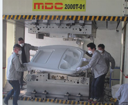
In modern composite manufacturing, product quality is no longer determined solely by mold design or raw materials. The performance of the compression molding machine itself plays a decisive role in controlling curing behavior, dimensional accuracy, mechanical properties, and long-term production consistency.

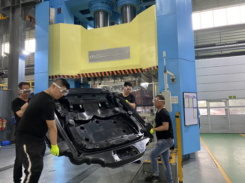
Whether manufacturing SMC automotive body panelsEV battery enclosuresBMC electrical components, or FRP water tank panels, every major machine component contributes directly to the quality of the finished part.

For this reason, leading composite manufacturers no longer view a compression molding press as simply a hydraulic machine. Instead, it is regarded as a highly integrated production system where pressure control, temperature uniformity, alignment precision, and digital process monitoring work together to eliminate defects and maximize production stability.

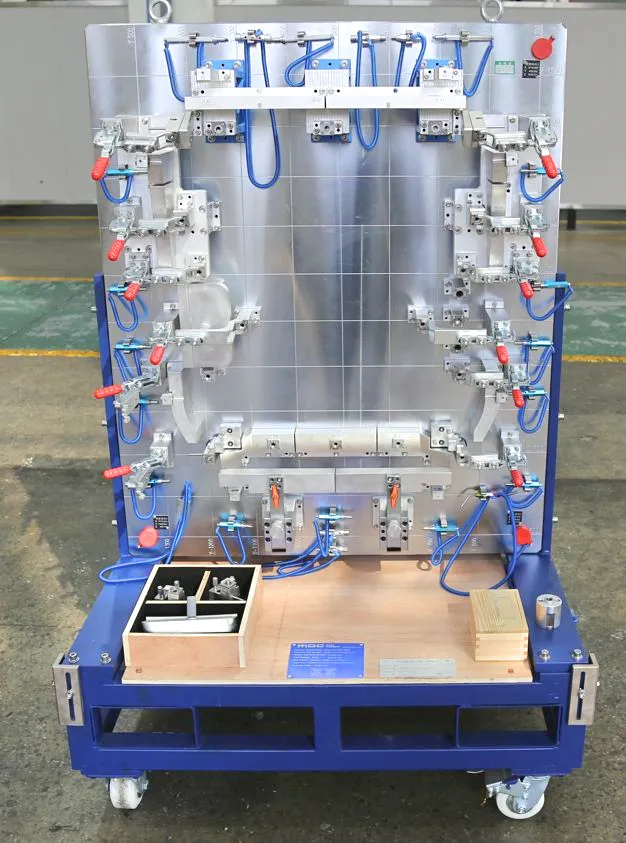
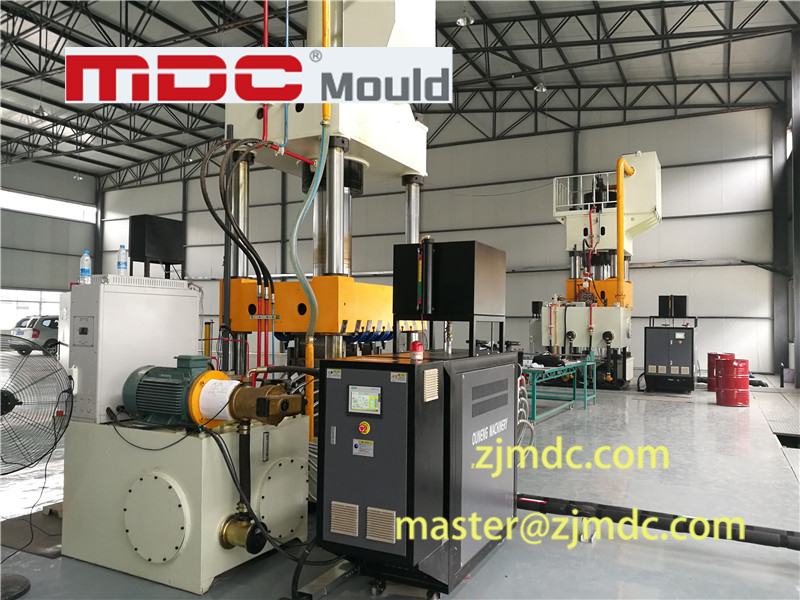
compression-molding

Why Machine Design Matters in Compression Molding

Many common composite molding defects—including porosity, blistering, under-curing, warpage, flash formation, dimensional variation, and inconsistent mechanical properties—can often be traced back to machine performance rather than mold design alone.

Modern compression molding machines are therefore engineered not only to generate force, but also to precisely control pressure profiles, platen temperature distribution, mold alignment accuracy, and real-time process monitoring.

Understanding the relationship between machine components and part quality is essential for achieving reliable manufacturing performance.

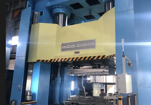
High-Tonnage Hydraulic System: Pressure and Multi-Stage Velocity Control

The hydraulic system is often considered the heart of a compression molding machine. However, its importance extends far beyond simply generating clamping force.

Modern compression molding presses utilize high-capacity hydraulic cylinders, servo-driven pumps, and precision proportional valves to create highly controlled pressure and velocity profiles throughout the molding cycle.

Rather than moving at a constant speed, the ram typically follows a carefully programmed multi-stage motion sequence:

  • Rapid closing approach
  • Controlled material contact
  • Degassing phase
  • Progressive compression phase
  • High-pressure curing phase
  • Pressure holding stage

This multi-stage velocity profile is particularly important when molding SMC and BMC materials.

During the early stages of mold closing, trapped air must be allowed to escape from the cavity. If excessive pressure is applied too quickly, air can become trapped inside the composite charge, resulting in internal porosity, blistering, and surface defects.

By carefully controlling closing speed and compression pressure, the hydraulic system enables efficient degassing before full compaction occurs.

During the curing phase, stable pressure distribution ensures proper resin flow, fiber consolidation, and dimensional accuracy throughout the entire component.

This is especially critical for large automotive exterior panels, EV battery covers, and structural composite components where internal voids can significantly reduce mechanical performance.

Smart Zoned Heating Platens: The Ultimate Factor in Cure Uniformity

Among all machine components, the heating platen system may have the greatest influence on composite part quality.

While mold designers often focus on cavity geometry and material flow, resin curing behavior is fundamentally governed by temperature control.

Modern compression molding machines utilize electrically heated platens, oil-heated platens, or steam-heated systems designed to maintain highly uniform temperature distribution across the entire molding surface.

Advanced zoned heating systems can often achieve temperature control accuracy within approximately ±1°C across large mold areas.

This level of thermal precision is essential for ensuring synchronized resin curing throughout the mold cavity.

Without uniform heating, different regions of the molded part may cure at different rates. Uneven curing generates localized residual stresses that can ultimately cause:

  • Warpage
  • Dimensional instability
  • Surface distortion
  • Fiber print-through
  • Reduced mechanical performance

For large SMC automotive body panels, battery enclosure covers, and BESS energy storage cabinet components, synchronized curing is critical for maintaining dimensional accuracy and surface quality.

By eliminating thermal gradients across the mold surface, high-precision platens help manufacturers achieve superior flatness, reduced internal stress, and highly consistent production results.

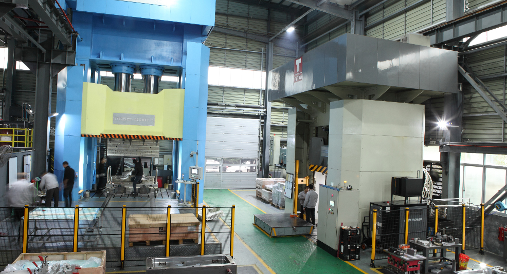
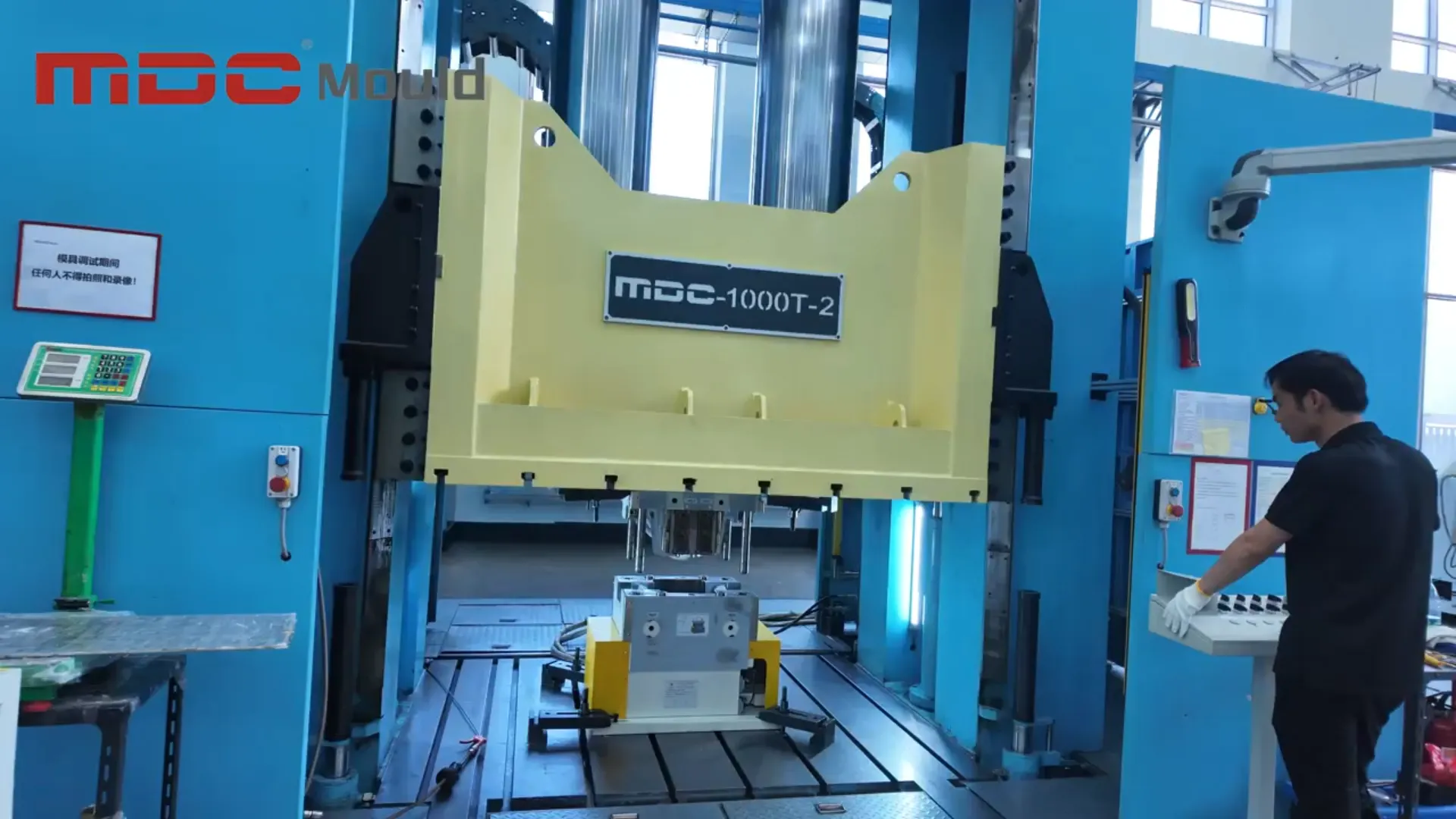
compression-mould-machine

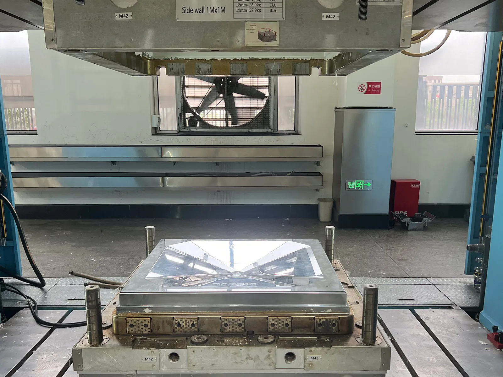
Precision Guide Pillars and Bushings: Protecting Mold Alignment and Shear Edges

The movement accuracy of the machine slide or ram directly influences mold life and product quality.

During every molding cycle, the moving platen must travel vertically while maintaining perfect alignment with the stationary mold half.

To achieve this, compression molding machines utilize precision-engineered guide pillarsguide bushings, and advanced guiding systems.

Their function extends far beyond simple motion guidance.

In modern SMC tooling, many molds incorporate highly precise shear edge designs that help control flash formation and improve material flow behavior.

These shear edges often operate with extremely small clearances.

Even slight platen misalignment can create serious problems:

  • Excessive flash formation
  • Premature shear edge wear
  • Mold damage
  • Reduced dimensional accuracy
  • Increased maintenance requirements

For high-volume automotive composite molds, alignment errors measured in only a few microns can significantly affect both mold longevity and product consistency.

High-precision guiding systems therefore serve as a critical safeguard for mold protection and long-term production stability.

Programmable PLC Control Systems with Real-Time Data Logging

The most advanced compression molding machines are no longer controlled solely through mechanical adjustments. Instead, they operate through sophisticated PLC-based control architectures integrated with intelligent Human Machine Interface (HMI) systems.

These digital control systems continuously monitor and record every critical production parameter throughout the molding cycle.

Key process variables include:

  • Press force
  • Hydraulic pressure
  • Ram position
  • Closing speed
  • Mold temperature
  • Cure time
  • Cycle duration

Rather than simply displaying machine status, these systems create a complete digital manufacturing record for every molded part.

This real-time data logging capability enables true closed-loop process control, allowing manufacturers to detect deviations immediately and maintain highly repeatable production conditions.

For automotive, aerospace, and energy storage applications, digital traceability has become an essential supplier qualification requirement.

OEMs increasingly require manufacturers to provide detailed process records demonstrating that every part was produced within specified process windows.

Without comprehensive data acquisition and traceability capabilities, entering high-end automotive EV supply chains or aerospace programs becomes increasingly difficult.

How Machine Components Work Together to Eliminate Composite Defects

The true performance of a compression molding machine is not determined by any single component. Instead, quality results are achieved through the interaction of pressure control, temperature management, alignment precision, and intelligent process monitoring.

Machine ComponentPrimary Quality FunctionDefects Prevented
Hydraulic SystemMulti-stage compression and degassing controlPorosity, blistering, voids
Heating PlatensSynchronized curing and thermal uniformityWarpage, residual stress, distortion
Guide Pillars & BushingsMold alignment accuracyFlash, shear edge wear, mold damage
PLC Control SystemClosed-loop process monitoringProcess instability and quality variation

The Future of Compression Molding Machines

As composite materials continue expanding into electric vehicles, battery enclosures, hydrogen energy systems, aerospace structures, and infrastructure applications, compression molding equipment is evolving from traditional hydraulic presses into intelligent manufacturing platforms.

Future systems will incorporate AI-assisted process optimization, predictive maintenance, digital twin technology, and fully integrated factory data networks.

However, regardless of future innovations, the fundamental relationship remains unchanged: superior composite products begin with superior machine control.

Conclusion

The parts of a compression molding machine do far more than support machine operation. Each component directly influences composite part quality, production efficiency, and long-term manufacturing reliability.

From multi-stage hydraulic pressure control and precision heating platens to alignment systems and real-time digital process monitoring, every subsystem contributes to defect prevention and product consistency.

For manufacturers producing SMC automotive components, EV battery enclosures, BMC electrical parts, and advanced composite structures, understanding these machine-to-quality relationships is essential for achieving world-class molding performance.

At MDC Mould, we believe that successful composite manufacturing is built upon the combination of advanced mold engineering and precision-controlled molding technology, ensuring reliable production and superior product quality across every application.

Disadvantages of Compression Molding: Overcoming Process Limitations

Understand the disadvantages of compression molding. Explore tooling limitations, flash trimming costs, and how modern SMC/BMC engineering solves key defects.

Compression molding remains one of the most widely used manufacturing processes for producing SMC moldsBMC molds, carbon fiber composite components, and large structural thermoset parts.

Due to its advantages in producing lightweight, high-strength, and cost-effective composite products, compression molding is extensively applied in:

  • Automotive manufacturing
  • Electrical components
  • Construction materials
  • SMC water tanks
  • Bathroom products
  • Rail transportation
  • Aerospace composite structures

However, despite its many advantages, manufacturers often ask an important question:

What are the disadvantages of compression molding?

Like any manufacturing technology, compression molding has certain process limitations and engineering challenges. Understanding these disadvantages is critical for improving mold design, optimizing production efficiency, and enhancing composite product quality.

Fortunately, with advances in composite molding technology, many traditional compression molding problems can now be significantly reduced through better tooling engineering, optimized process control, and advanced material systems.

1. Longer Cycle Time Compared with Injection Molding

One of the most commonly discussed disadvantages of compression molding is its relatively long production cycle.

Unlike injection molding, where molten material rapidly fills the cavity, compression molding requires:

  • Material loading
  • Mold closing
  • Pressure application
  • Heat curing
  • Cooling
  • Demolding

For thermoset materials such as SMC (Sheet Molding Compound) and BMC (Bulk Molding Compound), the curing process often increases total cycle time.

Depending on product thickness and material type, a molding cycle may range from several minutes to much longer for large structural components.

Modern Solutions

Today, advanced manufacturers improve cycle efficiency through:

  • Optimized mold heating systems
  • Automated material loading
  • High-speed hydraulic presses
  • Intelligent temperature control
  • Preheating technologies
  • Automated demolding systems

Modern compression molding systems can significantly reduce production time while maintaining stable product quality.

compression molding

2. Flash Formation and Additional Trimming Requirements

Another common compression molding limitation is the formation of flash around molded parts.

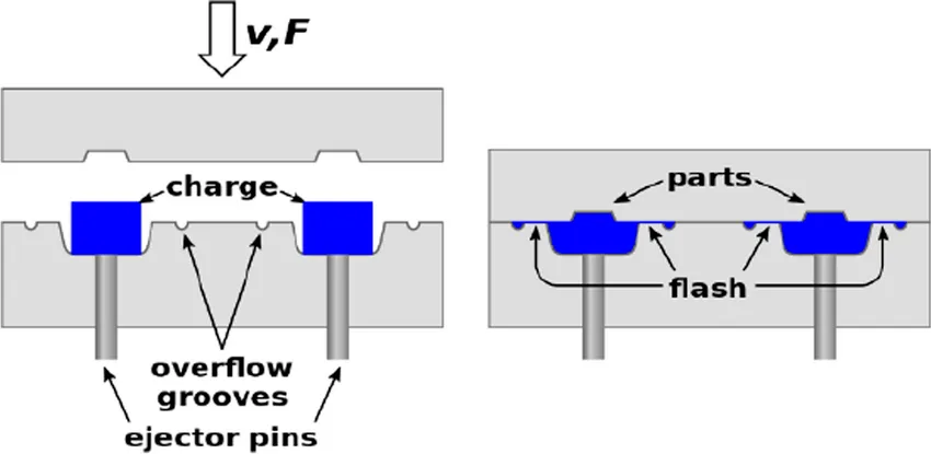
During the compression process, excess material may flow outside the mold cavity, creating thin unwanted edges commonly referred to as flash.

Flash formation may result in:

  • Additional manual trimming
  • Increased labor cost
  • Reduced production efficiency
  • Material waste
  • Secondary finishing operations

Modern Solutions

Advanced compression mold design now minimizes flash through:

  • Precision cavity machining
  • Improved sealing structures
  • Optimized material charge placement
  • High-precision mold alignment systems
  • Automated trimming technologies

Precision CNC machining and improved mold tolerances help significantly reduce excess flash generation.

3. Tooling Investment Can Be High

Although compression molding is generally cost-effective for mass production, initial tooling investment may still be significant for large or complex composite molds.

High-quality compression molds often require:

  • Large steel structures
  • Precision CNC machining
  • Complex heating systems
  • Vacuum systems
  • High-polish surface finishing
  • Structural reinforcement engineering

Large automotive SMC molds and carbon fiber compression molds may involve considerable engineering and manufacturing costs.

Modern Solutions

Advanced mold engineering helps improve tooling return on investment through:

  • Longer mold service life
  • Multi-cavity mold designs
  • Modular tooling structures
  • Improved wear resistance
  • Optimized maintenance systems

For high-volume production, the cost per part becomes highly competitive over time.

4. Challenges with Highly Complex Geometries

Compared with injection molding, traditional compression molding may have limitations when producing:

  • Deep undercuts
  • Very small holes
  • Complex internal structures
  • Extremely intricate geometries

This limitation mainly results from the flow characteristics of thermoset composite materials.

Insufficient material flow may lead to:

  • Incomplete filling
  • Void formation
  • Fiber misalignment
  • Surface defects

Modern Solutions

Modern composite manufacturing technologies now improve molding complexity through:

  • Advanced flow simulation analysis
  • Vacuum-assisted compression molding
  • Improved charge pattern design
  • Hybrid molding technologies
  • Multi-stage compression processes

Advanced engineering allows manufacturers to produce increasingly complex composite structures with high dimensional accuracy.

compression molding process

5. Material Waste and Process Sensitivity

Although compression molding generally offers good material utilization, process inconsistency may still result in:

  • Excess material usage
  • Part defects
  • Uneven fiber distribution
  • Surface imperfections
  • Dimensional instability

The quality of compression molded products is highly influenced by:

  • Material charge weight
  • Mold temperature
  • Pressure distribution
  • Curing time
  • Fiber orientation

Modern Solutions

Today’s intelligent molding systems improve consistency through:

  • Automated process monitoring
  • Real-time temperature control
  • Digital pressure management
  • Simulation-based mold optimization
  • AI-assisted process analysis

These technologies significantly improve product repeatability and reduce scrap rates.

6. Difficult Recycling of Thermoset Composite Materials

One important challenge in thermoset compression molding is recyclability.

Unlike thermoplastic materials, thermoset composites undergo irreversible chemical curing during molding.

As a result:

  • Scrap materials are difficult to remelt
  • Reprocessing is limited
  • Defective parts often cannot be reused
  • Waste management becomes more complex

Modern Solutions

The composite industry is actively developing:

  • Recyclable thermoplastic composites
  • Low-waste molding technologies
  • Sustainable resin systems
  • Hybrid composite recycling solutions

New sustainable composite materials are expected to improve the environmental performance of future compression molding systems.

7. Mold Temperature and Process Control Requirements

Compression molding requires highly controlled processing conditions.

Improper control of:

  • Mold temperature
  • Pressure
  • Curing speed
  • Cooling rate

may lead to:

  • Warping
  • Shrinkage
  • Surface waviness
  • Internal stress
  • Dimensional inaccuracy

Modern Solutions

Advanced process optimization technologies now include:

  • Finite element analysis (FEA)
  • Mold flow simulation
  • Integrated thermal management systems
  • Digital process control systems
  • Automated pressure regulation

These technologies greatly improve molding stability and composite product quality.

Why Compression Molding Remains Highly Competitive

Despite these challenges, compression molding remains one of the most important manufacturing technologies for high-performance composite products.

Compared with many alternative processes, compression molding still offers:

  • Excellent strength-to-weight ratio
  • Low material waste
  • Large structural part capability
  • High production repeatability
  • Cost-effective mass production
  • Excellent surface finish

This is why compression molding continues to play a major role in:

  • Automotive lightweighting
  • EV battery enclosures
  • SMC bathroom products
  • Electrical insulation components
  • Aerospace composite structures
  • Construction composite systems

Conclusion

Understanding the disadvantages of compression molding is essential for improving product quality, optimizing tooling systems, and enhancing manufacturing efficiency.

While traditional compression molding may involve challenges such as:

  • Longer cycle times
  • Flash trimming
  • Tooling complexity
  • Geometry limitations
  • Thermoset recyclability issues

modern advancements in:

  • SMC molding technology
  • BMC compression molding
  • Process simulation
  • Precision mold engineering
  • Intelligent manufacturing systems

are continuously overcoming these limitations.

As composite manufacturing technology evolves, compression molding will remain a critical solution for producing lightweight, durable, and high-performance composite components across multiple industries.

What Is the Difference Between Transfer Mold and Compression Mold?

Compare transfer molding vs. compression molding. Explore differences in tooling design, production costs, and component complexity for SMC/BMC composites.

As global manufacturing industries continue moving toward lightweight engineeringadvanced thermoset composites, and high-performance structural materials, both transfer molding and compression molding have become essential technologies in modern industrial production.

From SMC automotive panels and carbon fiber structural components to electrical insulation systems and precision thermoset parts, manufacturers must choose the correct molding process to optimize:

  • Product quality
  • Production efficiency
  • Tooling investment
  • Material performance
  • Surface finish
  • Dimensional stability

At MDC Mould, we specialize in advanced SMC moldBMC moldcompression toolingcarbon fiber mold, and composite mold manufacturing solutions for global industries.

Quick Answer:

The main difference between a transfer mold and a compression mold is how the material enters the mold cavity.

In compression molding, the material is placed directly into the mold cavity before closing.

In transfer molding, the material is first heated inside a transfer chamber and then forced into a closed cavity through runners and gates.

What Is Compression Molding?

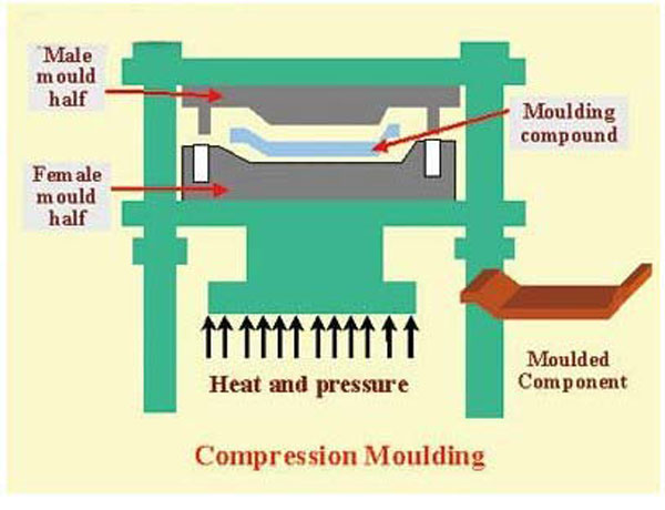
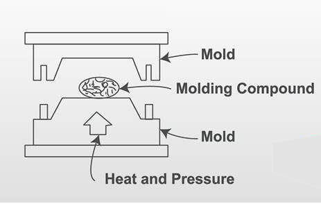
Compression molding is a manufacturing process where a pre-measured charge of thermoset or composite material is placed directly into an open heated mold cavity.

The mold closes under high pressure, forcing the material to flow and fill the cavity while heat cures the material into its final shape.

Compression molding is widely used for:

  • SMC molding
  • BMC molding
  • Carbon fiber molding
  • GMT molding
  • LFT molding
  • Thermoset composite production
  • Rubber compression molding

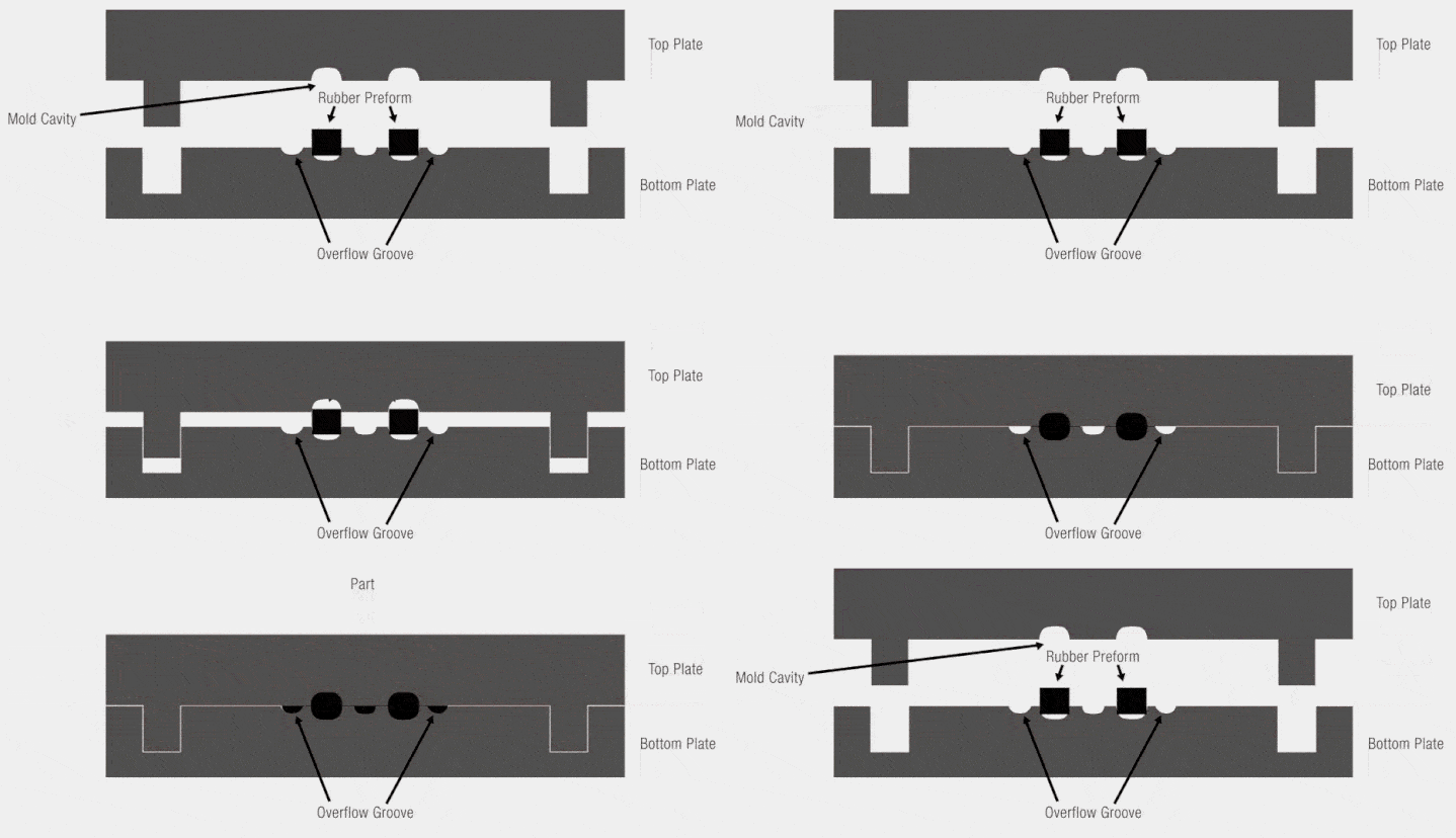
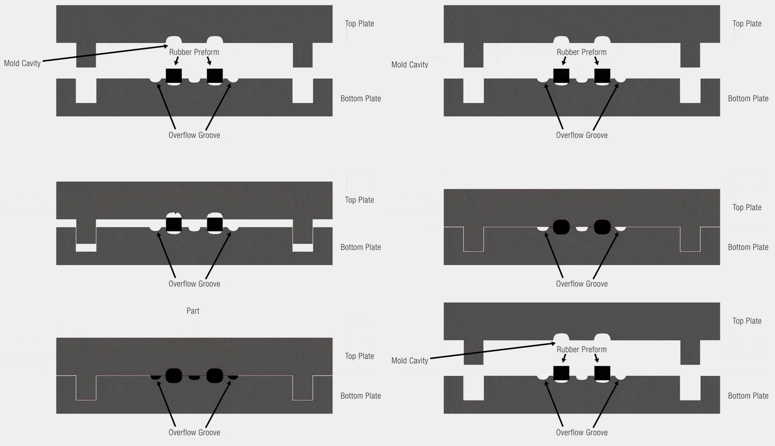
Compression Molding Process

  1. Material preparation
  2. Charge placement into mold cavity
  3. Mold closing
  4. Compression and material flow
  5. Heat curing
  6. Mold opening
  7. Demolding
  8. Trimming and finishing
compression moulding process

Advantages of Compression Mold Technology

  • Suitable for large structural parts
  • Excellent fiber length retention
  • Lower tooling cost
  • Lower material waste
  • Strong mechanical performance
  • Ideal for SMC and BMC materials
  • Suitable for automotive lightweight structures

Disadvantages of Compression Molding

  • Longer cycle time
  • Flash trimming may be required
  • Less suitable for highly intricate geometries
  • Manual loading may reduce automation level

What Is Transfer Molding?

Transfer molding is a thermoset molding process that combines characteristics of both compression molding and injection molding.

Instead of placing the material directly into the cavity, the material is loaded into a separate transfer chamber. A plunger forces the heated material through runners and gates into the closed mold cavity.

Transfer Molding Process

  1. Material loading into transfer chamber
  2. Mold cavity closing
  3. Plunger pressure application
  4. Material transfer through runners
  5. Curing inside cavity
  6. Mold opening
  7. Part ejection
  8. Runner trimming
RTM

Advantages of Transfer Mold Technology

  • Excellent dimensional precision
  • Superior surface finish
  • Reduced flash
  • Ideal for insert molding
  • Suitable for complex geometries
  • Better consistency for small precision components

Disadvantages of Transfer Molding

  • Higher tooling cost
  • More complex mold structure
  • Higher material waste
  • Not ideal for large structural composite parts
  • Fiber damage may occur during transfer flow

Core Difference Between Transfer Mold and Compression Mold

FactorCompression MoldTransfer Mold
Material LoadingDirectly into cavityInto transfer chamber
Mold Status During FillingOpenClosed
Material FlowCompression flowForced transfer flow
Tooling ComplexitySimplerMore complex
Tooling CostLowerHigher
Material WasteLowerHigher
Surface FinishGoodExcellent
PrecisionModerateHigh
Suitable Part SizeLarge partsSmall-medium parts
Fiber PreservationExcellentModerate
AutomationModerateHigher
Best ApplicationsStructural composite partsPrecision thermoset parts

Compression Mold Structure

A typical compression mold usually consists of:

  • Upper mold
  • Lower mold
  • Heating system
  • Guide pillars
  • Cooling channels
  • Venting system
  • Ejection system

For advanced SMC tooling and BMC tooling, engineers must optimize:

  • Material flow
  • Fiber orientation
  • Thermal balance
  • Shrinkage compensation
  • Demolding angles
  • Surface quality

Transfer Mold Structure

A typical transfer mold includes:

  • Transfer chamber
  • Plunger system
  • Runner channels
  • Gate system
  • Closed mold cavity
  • Heating system
  • Venting channels
  • Ejection system

Because of the complex runner and gate system, transfer molds generally require:

  • Higher machining precision
  • More advanced sealing technology
  • More complex thermal management
  • Higher maintenance standards

Material Compatibility Comparison

Compression Molding Materials

  • SMC (Sheet Molding Compound)
  • BMC (Bulk Molding Compound)
  • Carbon fiber prepreg
  • GMT composites
  • LFT composites
  • Phenolic compounds
  • Rubber materials

Compression molding is particularly suitable for long-fiber reinforced composite materials because it preserves fiber integrity and mechanical strength.

Transfer Molding Materials

  • Epoxy compounds
  • Phenolic resins
  • Silicone materials
  • Electronic encapsulation compounds
  • Precision thermoset compounds

Transfer molding is generally better for lower-viscosity materials capable of flowing efficiently through runners and gates.

Applications of Compression Mold Technology

  • Automotive exterior panels
  • EV battery enclosures
  • Truck roof panels
  • SMC water tanks
  • Carbon fiber structural components
  • Aerospace interior panels
  • Railway composite structures
  • Industrial equipment housings
SMC foot plate mould

Applications of Transfer Mold Technology

  • Electronic encapsulation
  • Electrical switches
  • Precision industrial parts
  • Medical device components
  • Semiconductor packaging
  • Sensor housings
  • Electrical insulation systems

Why Compression Molding Dominates Composite Manufacturing

Modern lightweight industries increasingly rely on compression molding because it offers:

  • Excellent structural performance
  • Better fiber distribution
  • Lower production cost for large parts
  • Superior lightweight performance
  • Reduced material waste
  • Scalability for automotive production

This is why many global manufacturers use SMC moldBMC mold, and carbon fiber mold systems for advanced lightweight applications.

Future Trends in Transfer and Compression Molding

Compression Molding Trends

  • Automated SMC production lines
  • AI-assisted process optimization
  • Large integrated automotive structures
  • Fast-curing thermoset materials
  • Recyclable composite systems
  • EV lightweight component manufacturing

Transfer Molding Trends

  • Miniaturized electronic packaging
  • Multi-cavity precision production
  • High-speed encapsulation systems
  • Smart manufacturing integration
  • Advanced semiconductor applications

How to Choose Between Transfer Mold and Compression Mold

RequirementRecommended Process
Large composite structureCompression molding
Precision small componentTransfer molding
Long-fiber reinforcementCompression molding
Insert moldingTransfer molding
Lower tooling costCompression molding
Complex geometryTransfer molding
Automotive exterior panelCompression molding
Electronic encapsulationTransfer molding

MDC Mould’s Compression Mold Expertise

As a professional manufacturer of advanced composite mold systems, MDC Mould specializes in:

  • SMC mold manufacturing
  • BMC mold systems
  • Compression tooling engineering
  • Carbon fiber mold solutions
  • Automotive composite molds
  • EV battery enclosure molds
  • Thermoset composite tooling
  • FRP tooling systems

Using advanced CNC machining, CAE simulation, and precision manufacturing technologies, MDC provides reliable composite mold solutions for global industries.

Conclusion

Both transfer molding and compression molding are critical thermoset manufacturing technologies, but they serve different industrial purposes.

Compression molding is ideal for:

  • Large structural composite parts
  • Automotive lightweight components
  • SMC and BMC applications
  • Fiber-reinforced thermoset products

Meanwhile, transfer molding excels in:

  • Precision thermoset components
  • Electronic encapsulation
  • Insert molding
  • Complex small geometries

As global industries continue advancing toward lightweight manufacturing, electrification, and smart industrial production, both technologies will remain essential in the future of advanced composite manufacturing.

What Is Compression Molding Used For?

Discover high-performance compression molding for EV, aerospace, and medical sectors. Optimize complex parts with SMC/BMC and carbon fiber tooling by MDC Mould.

As industries continue moving toward lightweight engineeringhigh-performance composite materials, and sustainable manufacturing, compression molding has become one of the most important production technologies in modern industrial manufacturing.

From automotive composite components and EV battery enclosures to SMC water tanks, aerospace structures, and electrical insulation systems, modern compression molding technology enables the production of strong, lightweight, and corrosion-resistant composite parts.

At Zhejiang MDC Mould Co., Ltd., we specialize in manufacturing advanced:

  • SMC molds
  • BMC molds
  • Compression molds
  • Composite tooling
  • Carbon fiber molds
  • Thermoforming molds
  • GMT and LFT tooling systems
Compression molding process and composite tooling

Quick Answer:

Compression molding is used to manufacture lightweight, high-strength, heat-resistant, and corrosion-resistant composite parts for industries such as automotive, aerospace, electrical, construction, renewable energy, and medical equipment manufacturing.

What Is Compression Molding?

Compression molding is a manufacturing process where composite material is placed into a heated mold cavity and compressed under high pressure to form a finished component.

The process is widely used for:

  • SMC molding
  • BMC molding
  • Carbon fiber molding
  • Thermoset composite molding
  • Large structural composite panels
  • Electrical insulation components

Compared with many traditional plastic molding methods, compression molding provides superior structural strength and excellent dimensional stability for large industrial components.

How Does the Compression Molding Process Work?

The standard compression molding process generally includes:

  1. Preparing composite material charges
  2. Loading materials into the mold cavity
  3. Closing the heated compression mold
  4. Applying pressure and temperature
  5. Curing the composite material
  6. Opening the mold
  7. Demolding and trimming the finished product

The process allows the material to flow evenly inside the cavity while achieving high mechanical strength and stable surface quality.

SMC compression mold manufacturing

Major Industries Using Compression Molding

1. Automotive Industry

The automotive sector is one of the largest users of SMC molds and compression tooling.

Compression molded composite parts help manufacturers reduce vehicle weight while improving energy efficiency and structural performance.

Typical Automotive Compression Molded Parts

  • EV battery enclosures
  • SMC battery covers
  • Roof panels
  • Truck body components
  • Engine splash shields
  • Trunk lids
  • Automotive exterior panels
  • Underbody aerodynamic panels
  • Pickup truck cargo systems

As electric vehicles continue expanding globally, lightweight composite manufacturing technologies are becoming increasingly important.

Automotive SMC mold and compression tooling

2. Aerospace Industry

The aerospace industry uses advanced carbon fiber molds and composite tooling to manufacture lightweight structures with exceptional strength-to-weight ratios.

  • Aircraft cabin panels
  • Structural aerospace components
  • Satellite composite parts
  • Radome systems
  • High-temperature resistant panels

Carbon fiber compression molding provides excellent fatigue resistance and dimensional precision for aerospace applications.

3. Electrical & Electronics Industry

BMC molding is widely used in electrical applications because of its excellent insulation and flame resistance.

ApplicationAdvantages
Electrical switch housingsExcellent insulation performance
Motor componentsHeat resistance
Transformer insulation systemsDimensional stability
Circuit breaker partsFlame retardant properties

4. Construction & Infrastructure

Compression molding is widely used for manufacturing corrosion-resistant construction products such as:

Compared with steel materials, composite structures provide:

  • Longer service life
  • Lower maintenance costs
  • Better corrosion resistance
  • Lightweight installation advantages
SMC water tank mold and GRP composite tooling

5. Medical Equipment Manufacturing

Medical industries increasingly adopt precision compression molds for lightweight equipment housings and structural components.

  • MRI machine covers
  • Medical device enclosures
  • Radiation-resistant panels
  • Hospital electrical systems
  • Clean-room compatible structures

6. Renewable Energy Applications

Renewable energy systems require lightweight and weather-resistant composite structures.

Compression molded components are widely used in:

  • Wind turbine systems
  • Solar equipment structures
  • Energy storage enclosures
  • Industrial composite covers

Common Materials Used in Compression Molding

Modern composite molding technologies support various advanced materials:

  • SMC (Sheet Molding Compound)
  • BMC (Bulk Molding Compound)
  • Carbon fiber composites
  • Glass fiber reinforced plastics
  • GMT materials
  • LFT materials
  • D-LFT composite systems

Advantages of Compression Molding

Main Benefits of Compression Molding

  • Excellent strength-to-weight ratio
  • High dimensional stability
  • Suitable for large structural components
  • Excellent corrosion resistance
  • Reduced material waste
  • Lower tooling cost for large parts
  • High production efficiency
  • Excellent surface quality
  • Strong electrical insulation performance

Why High-Precision Compression Tooling Is Important

The performance of composite products heavily depends on the quality of the mold itself.

High-precision compression tooling ensures:

  • Stable curing conditions
  • Accurate dimensions
  • Improved material flow
  • Reduced production defects
  • Longer mold lifespan
  • Better demolding performance

At MDC Mould, advanced CNC machining, precision polishing, and CAE analysis technologies are used to manufacture high-performance composite molds for global customers.

Composite mold and compression tooling production

Future Trends of Compression Molding

The future of compression molding technology is closely linked with:

  • Electric vehicle lightweighting
  • Carbon fiber industrialization
  • Large integrated composite structures
  • Sustainable manufacturing systems
  • Automated molding production lines
  • Advanced thermoset composite technologies

As global industries continue demanding stronger and lighter materials, advanced composite molding solutions will continue expanding rapidly.

Why Choose MDC Mould?

MDC Mould specializes in:

  • SMC mold manufacturing
  • BMC mold manufacturing
  • Compression tooling systems
  • Carbon fiber molds
  • Composite tooling solutions
  • Thermoforming molds
  • Automotive composite molds

Our engineering capabilities include:

  • CAE mold flow analysis
  • Precision CNC machining
  • Mirror surface polishing
  • Large-scale mold assembly
  • Composite product development support
  • Global technical cooperation

Conclusion

Compression molding is widely used in automotive, aerospace, electrical, construction, medical, and renewable energy industries because it enables the production of lightweight, durable, and high-performance composite parts.

With the rapid development of electric vehicles, sustainable manufacturing, and advanced composite materials, the demand for high-quality compression molds and composite tooling will continue growing globally.

As a professional manufacturer of SMC moldsBMC molds, and advanced compression tooling, MDC Mould continues supporting customers worldwide with high-precision composite manufacturing solutions.

Advanced Press Tooling for SMC & Composite Compression Molding

Explore professional press tooling solutions for composite manufacturing, including compression molds, SMC molds, BMC molds, and thermoset tooling.

In modern industrial manufacturing, press tooling plays a crucial role in producing high-precision components with consistent quality and structural integrity. From automotive structural parts to electrical enclosures and infrastructure components, press tooling enables manufacturers to shape materials using controlled heat and pressure within a press machine.

As industries increasingly adopt lightweight composite materials, advanced tooling technologies such as compression mold systemsSMC molds, and composite molds have become essential for high-efficiency mass production.Professional tooling manufacturers like MDC Mould specialize in designing and producing high-precision press tooling solutions for global industrial applications.

What Is Press Tooling?

Press tooling refers to specialized molds used within mechanical or hydraulic press machines to shape materials through compression, forming, or molding processes. The tooling system creates a controlled cavity where raw materials are transformed into finished products under pressure and temperature.

Typical materials used in press tooling production include:

  • Sheet Molding Compound (SMC)
  • Bulk Molding Compound (BMC)
  • Carbon fiber composite materials
  • Thermoset composite sheets
  • Thermoplastic structural materials
  • Metal forming materials

Using high-precision compression tooling, manufacturers can produce complex structural components with excellent dimensional accuracy and repeatability.

compression mould machine

Main Types of Press Tooling Used in Composite Manufacturing

SMC Mold (Sheet Molding Compound Mold)

SMC molds are widely used in the automotive and electrical industries. They enable the compression molding of glass-fiber reinforced composite materials into strong, lightweight components.

Typical SMC mold applications include:

  • Automotive exterior panels
  • EV battery enclosures
  • Engine splash shields
  • Structural composite components

BMC Mold (Bulk Molding Compound Mold)

BMC molds are commonly used to produce electrical insulation components and high-strength industrial parts. BMC materials offer excellent flame resistance and electrical insulation properties.

Common BMC mold applications:

  • Electrical connector housings
  • Switchgear components
  • Lighting fixtures
  • Industrial equipment enclosures

Composite Compression Mold

Composite compression molds are designed for advanced composite materials such as carbon fiber, fiberglass, and hybrid composites. These tools are essential for producing lightweight structural components with superior mechanical performance.

Learn more about professional composite tooling solutions at: Compression Mold Manufacturing

Key Components of a Professional Press Tooling System

Upper and Lower Mold Structure

Press tooling typically consists of two primary mold halves: the upper mold and the lower mold. These components create the mold cavity where material shaping occurs during the compression molding process.

Precision Mold Cavity

The cavity design determines the final geometry and structural features of the product. Proper cavity engineering ensures uniform material flow, reduces defects, and improves final product strength.

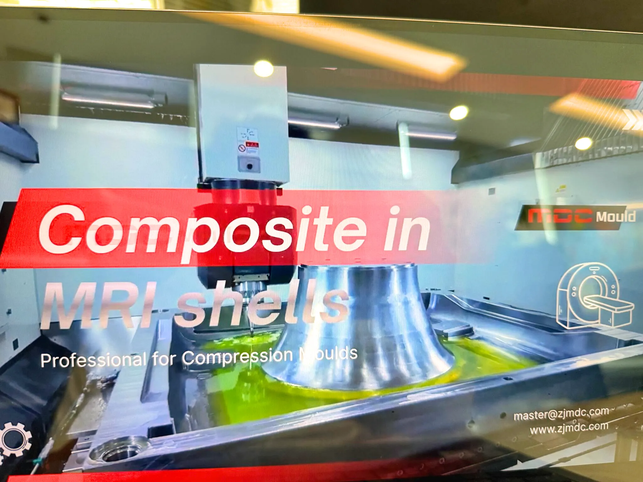
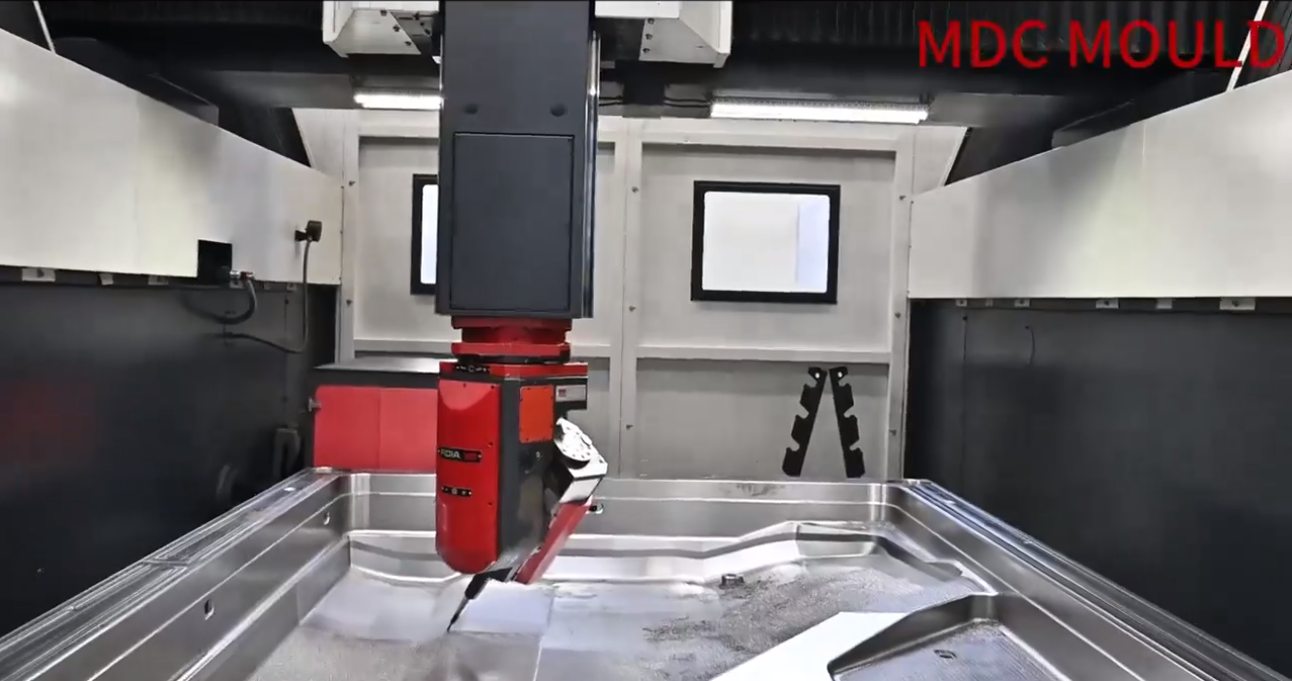
high speed milling

Heating System

Most thermoset composite molds integrate heating systems that maintain consistent curing temperatures. These heating systems may include:

  • Electric heating rods
  • Oil circulation heating channels
  • Temperature sensors
  • Thermal insulation layers

Ejection System

An effective ejection system ensures smooth demolding after the compression cycle. This may involve hydraulic ejectors, mechanical ejector pins, or pneumatic release mechanisms.

Materials Used in Press Tooling Manufacturing

High-quality press tooling requires durable materials capable of withstanding high pressure and repeated thermal cycles.

Tooling MaterialMain AdvantagesTypical Applications
P20 Tool SteelGood machinability and durabilityGeneral composite molds
H13 Tool SteelExcellent heat resistanceHigh-temperature compression molds
718 SteelHigh strength and wear resistanceLarge industrial press tooling
Aluminum ToolingLightweight and fast machiningPrototype molds

Industrial Applications of Press Tooling

Advanced press tooling is widely used across multiple industries requiring high-strength and lightweight components.

Automotive Industry

  • EV battery enclosure molds
  • Trunk board molds
  • Engine splash shield molds
  • Exterior body panels

Electrical Industry

  • Electrical connector molds
  • Switchgear insulation components
  • Lighting housings

Infrastructure and Construction

Advantages of High-Quality Press Tooling

Investing in professionally designed press tooling provides significant advantages for manufacturers.

  • High dimensional accuracy for consistent production quality
  • Improved manufacturing efficiency with optimized molding cycles
  • Superior surface finish for reduced post-processing
  • Long tooling lifespan due to high-quality steel materials
  • Lower production costs through high-volume manufacturing capability

Future Development Trends in Press Tooling Technology

The future of press tooling is being shaped by technological innovations and new material developments.

compression molds

FAQ About Press Tooling

What is the difference between press tooling and compression mold?

Press tooling is a general term for molds used in press machines, while a compression mold specifically refers to tooling designed for compression molding processes used with thermoset or composite materials.

What industries use press tooling?

Press tooling is widely used in automotive, aerospace, electrical equipment, infrastructure construction, and industrial manufacturing sectors.

How long does press tooling last?

High-quality press tooling manufactured from hardened tool steel can typically last hundreds of thousands to millions of molding cycles depending on production conditions.

Conclusion

Press tooling is a core technology in modern manufacturing, enabling the efficient production of high-precision components across multiple industries. With the increasing demand for lightweight materials and high-volume production, advanced tooling solutions such as SMC moldsBMC molds, and composite compression molds are becoming increasingly important.

Professional tooling manufacturers like MDC Mould continue to innovate in press tooling engineering, providing global customers with reliable, high-performance solutions for modern composite manufacturing.

Thermoforming vs. Thermoset Molding: A Compression Tooling Guide

In-depth guide to thermoforming moulds, thermoset molds, and compression molding processes. Learn differences, tooling design, materials, and applications for composite manufacturing.

As lightweight design, structural integration, and high-volume manufacturing continue to shape modern industries, advanced composite molding technologies have become essential. Among these technologies, thermoforming moldsthermoset molds, and compression molding tooling play a decisive role in determining part quality, production efficiency, and long-term durability.

This article provides a comprehensive overview of thermoforming toolingthermoset plastic molding, and the compression molding process, helping manufacturers select the most suitable mold solution for composite applications.

Understanding Thermoforming Moulds and Tooling

Thermoforming is a manufacturing process in which heated thermoplastic sheets are shaped over or into a mold using vacuum, pressure, or mechanical force. The thermoforming mould defines the final geometry, surface finish, and dimensional accuracy of the part.

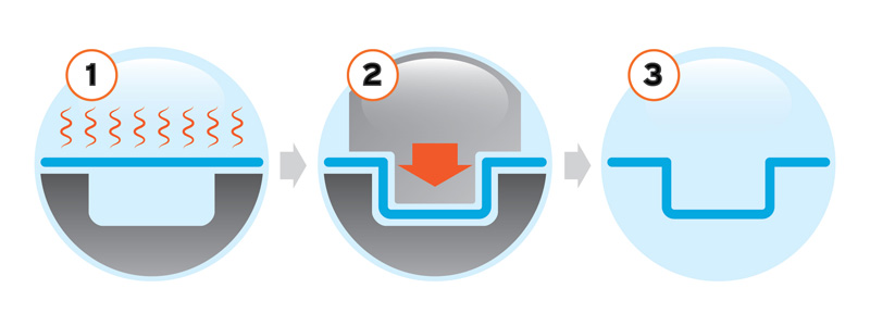
Thermoforming

Key Features of Thermoforming Molds

  • Designed for thermoplastic materials such as PP, ABS, PET, PMMA, and reinforced thermoplastics
  • Lower tooling cost compared to compression or injection molds
  • Fast heating and cooling cycles for high production efficiency
  • Suitable for large, thin-walled, and complex-shaped components

Modern thermoforming tooling is commonly manufactured from aluminum or composite materials, offering excellent thermal conductivity and dimensional stability.

Applications of Thermoforming Moulds

  • Automotive interior panels and trim components
  • Packaging trays and containers
  • Medical device housings
  • Industrial enclosures and lightweight covers

What Is a Thermoset Mold?

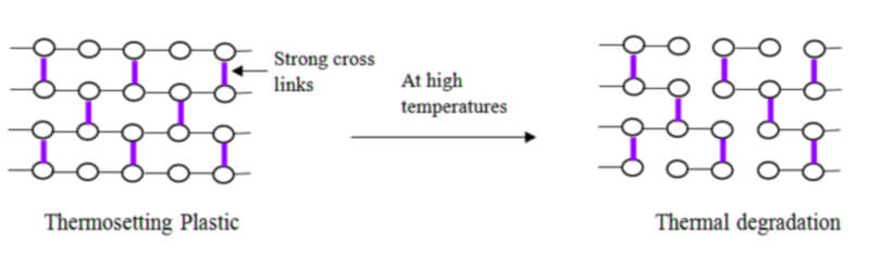
Unlike thermoplastics, thermoset plastics undergo an irreversible chemical curing process. Once cured, the material cannot be remelted or reshaped. A thermoset mold is specifically designed to withstand high pressure, elevated temperature, and repeated curing cycles.

Common Thermoset Materials

  • Sheet Molding Compound (SMC)
  • Bulk Molding Compound (BMC)
  • Epoxy resin systems
  • Phenolic and polyester resins

Thermoset molds are typically manufactured from hardened steel or high-strength alloy materials, ensuring long service life and excellent surface finish.

thermosetting-plastic-heated

Compression Molding Process Explained

Compression molding is one of the most widely used processes for thermoset composite manufacturing. In this process, a pre-measured charge of thermoset material is placed into a heated mold cavity and compressed under controlled pressure and temperature.

Steps in the Compression Molding Process

  1. Material loading into the mold cavity
  2. Mold closing and application of pressure
  3. Heat-induced curing of thermoset plastic
  4. Cooling and demolding of the finished part

Precision compression molding tooling ensures uniform material flow, minimal voids, and consistent mechanical properties across high-volume production runs.

Thermoforming Mold vs Thermoset Compression Mold

AspectThermoforming MoldThermoset Compression Mold
Material TypeThermoplasticThermoset Plastic
RecyclabilityHighLimited
Tooling CostLowerHigher
Structural StrengthModerateExcellent
Typical ApplicationsInterior panels, packagingAutomotive, electrical, structural components

Choosing the Right Tooling Solution

Selecting between thermoforming tooling and thermoset compression molding depends on several critical factors:

  • Mechanical performance requirements
  • Production volume and cycle time
  • Part thickness and structural complexity
  • Material recyclability and sustainability goals

For high-strength, load-bearing composite components, thermoset molds and compression molding remain the preferred solution. For lightweight, cost-sensitive, and recyclable applications, thermoforming molds offer outstanding advantages.

Advanced Composite Tooling Expertise at MDC

At Zhejiang MDC Mould Co., Ltd., we specialize in the design and manufacturing of thermoforming moldsthermoset molds, and compression molding tooling for global customers.

Our tooling solutions are widely used in automotive, electrical, energy storage, and industrial composite applications, ensuring high precision, long mold life, and stable mass production performance.

By combining advanced engineering, material expertise, and strict quality control, MDC delivers reliable composite mold solutions that support the future of lightweight manufacturing.

Next-Gen Compression Molds: Leveraging DMLS 3D Printing Technology

A comprehensive computational study demonstrates Direct Metal Laser Sintering (DMLS) as a viable, material-efficient alternative for compression mold and SMC mold manufacturing.

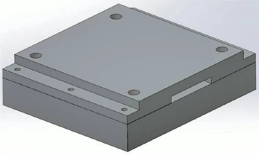
A recent computational analysis demonstrates that DMLS-produced metal molds—featuring honeycomb internal structures—can meet the structural and thermal demands of compression molding while reducing material usage by up to 74% compared to conventionally machined molds. This breakthrough has direct implications for high-precision SMC moldcompression mold, and advanced composite tooling applications.

compression-mold
Figure: Concept illustration of a DMLS honeycomb compression mold (image for illustration only).

Executive summary

Traditional compression mold fabrication relies on subtractive machining—CNC milling, turning, and EDM—to produce high-precision tooling. While accurate, these methods incur long lead times, high tooling steel consumption, and substantial material waste. The computational study summarized here evaluates Direct Metal Laser Sintering (DMLS) as an alternative production route for compression mold tooling. Key findings include:

  • DMLS mold with an internal honeycomb lattice achieved the design criterion of maximum deflection ≤ 0.001 inches under realistic molding pressures and temperatures.
  • The additive mold used approximately 74% less material than a conventionally machined equivalent.
  • Design freedom enabled by DMLS allows internal topology optimization, conformal cooling channel placement, and mass reduction without compromising stiffness.

1. Why DMLS matters for compression molds and SMC tooling

Direct Metal Laser Sintering (DMLS) is a powder-bed fusion metal additive manufacturing technology that constructs parts layer-by-layer using a focused laser to fuse metal powder. For compression mold and SMC mold manufacturers, DMLS offers several strategic advantages:

1.1 Material and cost efficiency

Additive lattice and honeycomb designs drastically reduce the volume of expensive tool steel required for large molds. The reported 74% material savings translate directly into lower material cost and reduced machining allowance when hybrid finishing (DMLS + CNC) is applied.

1.2 Geometric freedom and thermal control

DMLS enables features that are difficult or impossible to machine: internal lattices for light-weighting, integrated conformal cooling channels for thermal uniformity, and topology-optimized ribs that maximize stiffness per unit mass—capabilities that are especially beneficial for high-volume compression tooling.

1.3 Shorter development cycles

For R&D, prototype molds, or low-volume specialized tools, DMLS reduces lead times by removing complex multi-step machining processes. Iterations—such as channel geometry or reinforcement—can be implemented directly in the CAD model and printed without the need for expensive fixturing changes.

Mold-A-currently-existing-mold-CNC-manufactured

2. Computational approach: validating structural and thermal performance

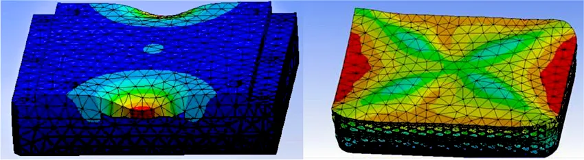
The study compared two mold concepts under identical molding conditions: a solid machined steel mold (reference) and a DMLS-manufactured mold with a honeycomb internal structure. Finite Element Analysis (FEA) evaluated mechanical deflection under molding pressure and thermal gradients representative of SMC compression cycles.

2.1 Structural analysis

Using linear and non-linear static simulations, the DMLS honeycomb mold maintained a maximum deflection below the stringent tolerance of 0.001 inches. The lattice geometry was tuned to concentrate material along principal stress paths while removing mass in low-stress regions.

2.2 Thermal analysis

Transient thermal simulations modeled heat input during a typical compression-curing cycle and subsequent cooling. The DMLS mold’s lower thermal mass (due to internal cavities) required active thermal management—implemented via conformal cooling channels—to ensure uniform cure and avoid hot spots. With conformal cooling, temperature differentials were within acceptable process windows.

2.3 Hybrid finishing strategy

The research emphasized a hybrid workflow: DMLS for the internal topology and near-net shape plus precision CNC finishing on critical mating surfaces. This approach ensures required surface finish and dimensional tolerances, while still preserving the material and time advantages of additive production.

3. Design recommendations for metal-AM compression molds

Based on computational results and best practices, the following guidelines are recommended when applying DMLS to compression mold tooling:

  • Topology-aware lattice design: Orient honeycomb or lattice reinforcement along primary load paths; avoid uniform porosity that undermines stiffness.
  • Conformal cooling integration: Place channels close to the cavity surface with controlled channel cross-sections to optimize heat extraction and cycle time.
  • Post-process planning: Design for CNC finishing allowance on sealing faces and parting lines; determine regions for stress-relief heat treatment to minimize residual stresses from AM.
  • Material selection: Use tool steels and maraging steels compatible with DMLS and post-heat-treatment to achieve required hardness for long tool life.
  • Quality assurance: Implement non-destructive testing (NDT) for internal porosity and coordinate metrology for cavity dimension verification.
moldflow

4. Manufacturing, sustainability, and cost considerations

While DMLS reduces raw material waste, manufacturers must evaluate machine time, powder costs, and post-processing expenses. Key considerations include:

  • Powder reuse strategies to minimize consumable costs.
  • Energy consumption of large-format DMLS machines versus conventional machining centers.
  • Tool life and maintenance: Ensure DMLS tool surface treatments or coatings to meet abrasive wear of SMC compounds.
  • Lifecycle analysis: Lowered steel usage and reduced machining waste contribute positively to environmental impact when balanced against AM energy use.

Practical conclusion: For mid-to-high complexity molds and R&D tooling, DMLS (combined with CNC finishing) is often economically and technically superior. For simple, very large-volume tooling with minimal internal features, traditional machining may still be preferable.

5. Implications for MDC Mould and the composite tooling industry

For a composite tooling specialist like MDC Mould, DMLS represents a strategic technology to complement existing CNC and EDM capabilities. Specific opportunities include:

  • Rapid prototype compression molds for SMC and BMC trials.
  • Optimized molds with conformal cooling to reduce curing cycle time and improve part consistency.
  • Customized lightweight tooling for large composite parts where handling and transport costs are significant.
  • Hybrid production lines in which DMLS cores are enclosed by conventionally manufactured cladding to balance cost and performance.

Adopting DMLS helps MDC strengthen its service offering for automotive SMC body panels, EV enclosures, structural composite parts, and specialized thermoforming tooling.

6. Recommended next steps for industrial adoption

  1. Run pilot projects combining DMLS-produced cores with CNC-finished faces for representative SMC mold designs.
  2. Perform full-cycle mold trials to validate wear resistance, demolding behavior, and part quality.
  3. Establish an internal AM design-for-manufacture (DfAM) guideline focused on lattice sizing, channel diameter, and post-processing sequences.
  4. Engage material suppliers to certify tool-steel powders specific to SMC process abrasion and thermal cycles.

Conclusion

This computational study demonstrates that DMLS is a technically viable option for modern compression mold manufacturing. When combined with conformal cooling and hybrid finishing strategies, DMLS molds can meet the strict structural and thermal demands of SMC compression processes while delivering substantial material savings and enhanced design freedom. For SMC mold and composite tooling providers, integrating DMLS into the manufacturing mix will open new possibilities for performance, sustainability, and rapid iteration.

Contact MDC Mould to learn how we integrate additive manufacturing with precision CNC finishing for next-generation compression molds: Contact us.

Core keywords: DMLS, compression mold, SMC mold, composite tooling, metal additive manufacturing, honeycomb mold, conformal cooling.

Curing Cycle Optimization in Compression Molding

Discover how Zhejiang MDC Mould optimizes the curing cycle in compression molding to enhance the strength, precision, and efficiency of composite components for automotive and industrial applications.

In the field of compression molding for composite materials, the curing cycle is one of the most decisive factors determining product performance, dimensional accuracy, and production efficiency. At Zhejiang MDC Mould Co., Ltd., mastering the curing cycle is not just process control—it is the essence of MDC’s precision engineering and its leadership in advanced composite mold manufacturing.

What Is the Curing Cycle in Compression Molding?

The curing cycle refers to the specific combination of time, temperature, and pressure applied to thermosetting composite materials within a compression mold. During this stage, materials such as SMC (Sheet Molding Compound) or BMC (Bulk Molding Compound) undergo crosslinking reactions that transform them from a semi-solid state into a rigid, durable component with stable mechanical properties.

A typical curing cycle involves three stages:

  • Heating phase: The mold is heated (130°C–170°C) to initiate resin polymerization.
  • Holding phase: The material remains under constant heat and pressure for full crosslinking.
  • Cooling phase: Controlled cooling solidifies the material and reduces internal stress before demolding.
compression-mould-machine

Why Curing Cycle Optimization Matters

For high-precision SMC and BMC molds designed by MDC, controlling the curing cycle is essential for ensuring consistent quality. If the curing cycle is too short, the resin may not fully crosslink, leading to surface or strength defects. If too long, unnecessary energy consumption and lower production efficiency result.

An optimized curing cycle ensures:

  • Stable mechanical performance — full crosslinking enhances strength and durability.
  • Dimensional precision — balanced curing prevents deformation and shrinkage.
  • Superior surface finish — precise curing leads to smooth, paint-ready surfaces.
  • Higher production efficiency — shorter cycles increase output and reduce costs.

Factors Influencing the Curing Cycle

The curing behavior within a compression mold depends on multiple factors:

  • Resin system: Polyester, epoxy, and phenolic resins each have distinct curing characteristics.
  • Reinforcement type: Fiber orientation, filler type, and content affect heat transfer.
  • Part geometry: Thicker sections require longer curing times to achieve uniformity.
  • Mold temperature control: Even heating ensures consistent curing throughout the cavity.
  • Venting and pressure: Proper venting avoids trapped air and ensures smooth resin flow.

MDC’s Engineering Approach to Curing Cycle Management

At MDC Mould, every compression mold is engineered with precise thermal management in mind. The company integrates finite element simulation and thermal flow analysis to predict temperature uniformity and curing behavior across complex cavities. This allows engineers to optimize the mold’s heating system and define ideal processing parameters before production begins.

MDC also utilizes:

  • Embedded thermal sensors for real-time temperature monitoring.
  • High-efficiency heating channels for rapid, uniform heat distribution.
  • Digital data systems linking process control with resin curing kinetics.

This approach ensures that each mold achieves an optimal balance between curing time, temperature, and pressure—guaranteeing reliable and repeatable composite part quality.

Case Study: SMC Roof Panel Mold for Electric Vehicle

In a recent project, MDC developed an SMC roof panel compression mold for a leading new energy vehicle manufacturer. By applying advanced thermal simulations and refining the curing schedule, MDC reduced the total cycle time by 20% while maintaining full crosslinking and high-gloss surface quality. The optimized curing cycle also minimized energy consumption and extended mold lifespan.

This success demonstrates MDC’s unique capability to merge curing cycle control with compression mold design excellence.

The Future of Curing Technology in Compression Molding

The next stage of curing optimization lies in smart manufacturing. MDC is developing intelligent compression molding systems that integrate AI-based thermal management, real-time curing monitoring, and predictive control algorithms. These innovations enable adaptive process adjustments—ensuring consistent curing performance, reduced energy use, and faster production cycles.

Conclusion

The curing cycle represents the heart of the compression molding process. Its precision defines not only the mechanical strength and dimensional accuracy of composite products but also overall manufacturing efficiency and sustainability. Through decades of experience and technological innovation, Zhejiang MDC Mould Co., Ltd. continues to advance the science of curing cycle optimization, delivering superior compression molds that empower global composite production with quality, consistency, and intelligence.

The Effect of Laser Cleaning on the Surface Quality of Compression Tooling Molds

Discover how laser cleaning improves the surface quality of compression tooling molds. Learn its effects on SMC molds, BMC molds, carbon fiber molds, and composite tooling, ensuring durability, precision, and sustainability.

Laser cleaning has emerged as a revolutionary technology for maintaining the surface quality of compression molds. This article explores its working principles, effects on tooling, and industrial applications across SMC moldsBMC molds, and composite molds.

Introduction

In high-precision industries, the surface quality of compression tooling molds directly impacts product performance and manufacturing efficiency. Over time, molds accumulate resin residues, release agents, carbon deposits, and oxides, leading to poor surface finishes and reduced part quality. Traditional methods such as chemical cleaning or sandblasting are either environmentally harmful or damaging to the mold surface.

By contrast, laser cleaning technology provides an eco-friendly, precise, and highly effective solution to restore mold integrity and prolong tool life.

Understanding Compression Tooling Molds

Compression molds are critical tools for shaping high-performance parts in industries such as automotive, aerospace, electronics, and consumer goods. These molds are commonly used with materials including:

  • SMC (Sheet Molding Compound)
  • BMC (Bulk Molding Compound)
  • GMT (Glass Mat Thermoplastic)
  • LFT (Long Fiber Thermoplastic)
  • Carbon fiber composites

The surface quality of these molds directly influences dimensional accuracy, demolding performance, and product aesthetics.

The Principle of Laser Cleaning

Laser cleaning uses high-intensity, short laser pulses to selectively remove contaminants without damaging the base mold material. The process is precise, non-contact, and environmentally friendly.

Key Benefits of Laser Cleaning

  • Micron-level precision for delicate tooling geometries
  • No abrasives or chemicals required
  • Preserves mold geometry and surface finish
  • Scalable and compatible with automation systems
SEM-images-and-3D-surface-profiles-of-a-S8-b-S10-c-S13-d-S14

Effects on Surface Quality of Compression Tooling Molds

1. Improved Surface Cleanliness

Laser cleaning effectively removes contaminants like resin, carbon, and oxides, restoring the mold surface and ensuring defect-free molded parts.

2. Preservation of Mold Geometry

Unlike abrasive cleaning, laser cleaning maintains the integrity of fine details and critical dimensions in SMC and BMC molds.

3. Surface Roughness Control

Laser parameters can be tuned to maintain smooth finishes or introduce micro-textures, improving resin flow and demolding performance.

4. Longer Mold Service Life

Reducing aggressive cleaning minimizes micro-cracks and surface fatigue, extending mold longevity.

5. Consistent Production Quality

Laser cleaning supports high-volume manufacturing by ensuring stable and repeatable mold conditions, especially in automotive compression molding.

Laser Cleaning vs. Traditional Cleaning Methods

Cleaning MethodLimitationsLaser Cleaning Advantages
Chemical cleaningHazardous waste, potential corrosionEco-friendly, no chemicals required
Sandblasting / Abrasive cleaningSurface wear, geometry alterationNon-abrasive, preserves mold accuracy
Manual polishingLabor-intensive, inconsistentAutomated, repeatable, precise
Ultrasonic cleaningSize limitations, liquid handlingDry, scalable, suitable for large molds

Industrial Applications of Laser Cleaning

  • SMC and BMC molds: Automotive body panels, battery covers, and electrical housings
  • Carbon fiber compression molds: Aerospace structural parts and sports equipment
  • Rubber compression molds: High-precision rubber seals and gaskets
  • Composite molds: Lightweight parts in automotive and renewable energy industries

Future Outlook

The future of mold maintenance lies in the integration of laser cleaning with automation and Industry 4.0 technologies. Robotics, AI-driven parameter control, and real-time surface monitoring will further improve efficiency and consistency.

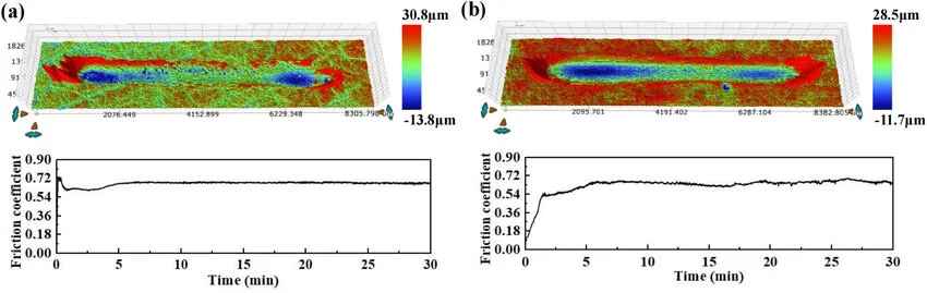
Friction-coefficient-evolution-during-tribological-testing-of-a-S0-and-b-S13-with

Conclusion

The effect of laser cleaning on the surface quality of compression tooling molds is profound. It ensures cleaner surfaces, longer mold life, consistent part quality, and environmental sustainability. For manufacturers using SMC molds, BMC molds, or carbon fiber molds, adopting laser cleaning is not only a technological upgrade but also a strategic move towards efficiency and sustainability.

Compression Molding Meets Insulation Boards

Learn how complete compression mold systems combined with high-performance insulation boards deliver structural stability, energy efficiency, and long-term durability for buildings, modular construction, automotive, and industrial applications.

Why pairing compression-molded composites with high-performance insulation boards sets a new benchmark in structural stability, energy efficiency, and lifecycle durability.On this page

1) What Is a Complete Compression Mold?

compression mold forms SMC, BMC, or FRP components under controlled heat and pressure. A complete compression mold system includes the tool, matched-metal dies, heating and cooling circuits, ejector mechanisms, and a validated process window (pressure–temperature–time) to achieve repeatable quality and short cycle times.

PrecisionDimensional tolerances down to ±0.2–0.5 mm (design dependent).

ThroughputOptimized cycle time via balanced thermal circuits and charge placement.

ConsistencyUniform pressure distribution minimizes porosity, warpage, and knit lines.

2) Insulation Boards: Types & Functional Roles

Insulation boards reduce heat transfer, stabilize temperatures, and enhance fire and acoustic performance when paired with molded composite skins or cores.

Board TypeCore BenefitsTypical Use with Molded PanelsNotes
PU (Polyurethane)High R-value per thickness; lightweightBuilding envelopes, modular wall/roof cassettesGood balance of cost and performance
XPS (Extruded Polystyrene)Low water uptake; strong compressive strengthFaçade panels, cold-chain enclosuresStable edges; easy machining
Phenolic FoamSuperior fire performance; low smokePublic buildings, transport interiorsHigh safety-critical environments
Mineral WoolNon-combustible; thermal + acousticFire-rated façades, industrial housingsExcellent sound dampening

Integration tip: When bonding insulation boards to compression-molded skins, select adhesives compatible with service temperatures and fire-rating targets (e.g., intumescent or low-smoke halogen-free chemistries).

3) Why the Combination Delivers Stability, Efficiency, and Durability

Stability

  • Structural integrity: Compression-molded skins provide high flexural and impact strength for panelized systems.
  • Thermal moderation: Insulation boards reduce thermal gradients and curb expansion-induced stress.
  • Dimensional control: Balanced laminate stacks and symmetric layups minimize warpage.

Efficiency

  • Factory throughput: Short, predictable molding cycles and modular panel assembly cut on-site time by 30–50%.
  • Energy savings: High R-values lower HVAC loads, reducing operating costs over the building lifecycle.
  • Design-to-manufacture: CAD/BOM standardization, BOM reuse, and jigs/fixtures improve repeatability and scale.

Durability

  • Environmental resistance: FRP skins resist corrosion, UV (with coatings), and chemicals.
  • Fire & moisture performance: Phenolic/mineral wool cores boost fire ratings; XPS limits water ingress.
  • Lifecycle longevity: Stable thermal envelope and robust skins reduce maintenance over decades.

4) High-Value Applications Across Industries

Modular Construction & Facades

  • Lightweight cassette panels with molded FRP skins and PU/XPS/phenolic cores.
  • Rapid on-site installation; consistent surface quality and weatherability.
  • Custom textures and colors via in-mold coatings (IMC) or gelcoats.

Automotive & Transport

  • EV battery covers, underbody shields, and HVAC housings with thermal and fire considerations.
  • Weight reduction improves range and fuel efficiency.
  • Acoustic damping via mineral wool cores in interior panels.

Electrical & Energy

  • Switchgear, inverter, and transformer enclosures with dielectric and fire requirements.
  • Insulated housings for renewable energy balance-of-plant components.

Aerospace & Industrial

  • Interior panels, bulkheads, and fairings with thermal/acoustic cores.
  • Offshore and corrosive environments benefit from FRP skins.
compression molding

5) Sustainability, Safety, and Compliance

  • Lower operational carbon: High thermal resistance trims HVAC energy use over the asset life.
  • Material efficiency: Net-shape molding reduces scrap; in-mold coatings eliminate multi-step finishing.
  • Fire & toxicity: Phenolic cores and halogen-free systems support stricter fire/smoke criteria.
  • End-of-life pathways: Mechanical recycling of FRP offcuts and thermal recovery options (policy-dependent).

6) Selection & Integration Guide

Design Checklist

  • Load cases: Wind/snow loads for façades; vibration/impact for transport; enclosure IP ratings for electrical.
  • Thermal envelope: Target U-value/R-value and local energy codes.
  • Fire performance: Specify test standards (e.g., reaction-to-fire, smoke development) required for occupancy type.
  • Durability: UV exposure class, chemical splash, salt spray, freeze–thaw cycles.

Process Recommendations

  • Charge strategy: Use pre-weighed SMC/BMC charges; optimize flow to avoid knit lines.
  • Thermal control: Segment mold channels; validate soak, cure, and cool-down for flatness.
  • Bonding & fastening: Surface prep (corona/abrade/solvent), adhesive selection (temperature, fire), and mechanical backup where needed.
  • QA/QC: Track SPC for thickness, fiber volume, void content; non-destructive testing for critical parts.

Pro tip: Combine in-mold coatings (IMC) for Class A surfaces with UV-stable topcoats on sun-exposed façades to maximize color retention and weathering.Request a tailored specification »

7) Frequently Asked Questions

Q1. How do I choose between PU, XPS, phenolic, and mineral wool?

PU/XPS for highest thermal efficiency and lightweight; phenolic where fire/smoke is critical; mineral wool for non-combustibility and acoustic control.

Q2. Can compression-molded skins achieve Class A finishes?

Yes—use IMC, optimized venting, and post-polish if needed. Tool surface quality and release systems are decisive.

Q3. What panel thickness is typical?

Common façade cassettes: 20–60 mm overall, depending on wind loads and U-value targets. Transport and enclosure panels vary by spec.

Get Specifications, Samples, or a Cost–Benefit Model

Need a bill of materials (BOM), sample set, or test plan for your application? Our engineering team can provide a project-specific laminate stack, insulation pairing, and processing window.

Contact Engineering