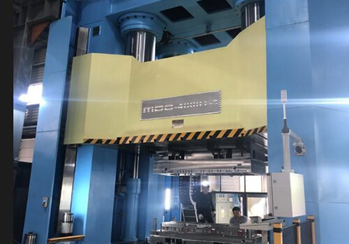
Tool life is one of the most important performance indicators in SMC compression molding. For automotive exterior panels, EV battery enclosures, sanitary ware products, electrical components, and structural composite parts, mold durability directly influences production costs, maintenance frequency, part consistency, and overall manufacturing profitability.
Many manufacturers assume that mold failure occurs because of poor maintenance or excessive production volume. In reality, most SMC molds begin losing performance long before they become unusable. Microscopic wear, thermal fatigue, cavity distortion, and surface degradation gradually accumulate until part quality can no longer meet specification requirements.
Understanding the primary failure mechanisms behind premature tooling wear allows manufacturers to improve mold design, optimize maintenance strategies, and significantly extend tooling service life.
Severe Glass Fiber Abrasion vs. Surface Hardness
One of the most common causes of premature SMC mold failure is the mismatch between glass fiber abrasion and mold surface hardness.
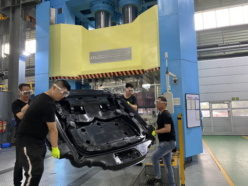
Typical SMC materials contain approximately 30% to 50% chopped glass fibers. During compression molding, these fibers flow across cavity surfaces under extremely high pressure while being carried by the resin system. Over thousands of molding cycles, this continuous movement creates severe scouring wear on mold surfaces.
Areas most vulnerable to abrasion include:
- Material charge zones
- Flow transition regions
- Rib structures
- Sharp corner geometries
- Parting line surfaces
If mold steels such as 1.2311 or 1.2738 are not properly surface engineered, the abrasive action of glass fibers can gradually damage the cavity finish. Surface roughness increases, release performance deteriorates, and dimensional accuracy begins to decline.
This wear mechanism often results in:
- Difficult demolding
- Surface defects
- Loss of Class A finish quality
- Dimensional inconsistency
- Increased maintenance frequency
To combat fiber abrasion, advanced SMC tooling frequently incorporates hard chrome plating, precision polishing, and specialized surface treatments capable of achieving surface hardness levels above 58 HRC while maintaining excellent release characteristics.

Thermal Fatigue and Stress Cracking from Poor Heat Management
Temperature control is often discussed from a product quality perspective, but it is equally critical for mold longevity.
Most SMC compression molds operate continuously between 140°C and 160°C. During production, molds repeatedly heat up, cool down, and experience thermal expansion cycles. If heating channels are poorly designed or temperature distribution is inconsistent, localized thermal gradients develop within the steel structure.
These temperature differences generate internal thermal stress as different areas of the mold expand and contract at different rates.
Over time, repeated thermal cycling may lead to:
- Thermal fatigue micro-cracking
- Surface cracking
- Loss of cavity precision
- Localized distortion
- Premature mold refurbishment
Large automotive components and EV battery enclosure molds are particularly sensitive because their extensive cavity surfaces make uniform temperature control more difficult.
Modern mold engineering increasingly relies on thermal simulation, optimized heating channel layouts, and zoned temperature control systems to minimize thermal stress and maximize tool life.
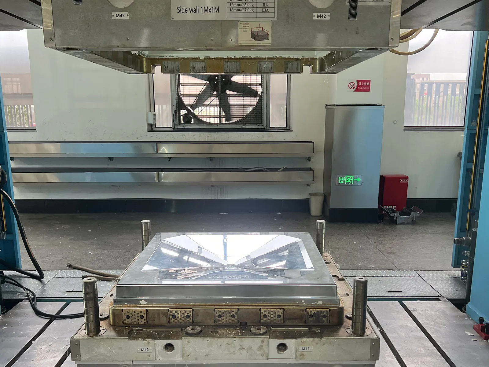
Shear Edge Micro-Chipping from Clamping Misalignment
The shear edge is one of the most critical and highly stressed features in an SMC compression mold.
In many automotive applications, shear edge clearances typically range between 0.03 mm and 0.05 mm. These extremely tight tolerances are necessary to control flash generation and maintain clean part edges.
However, if press alignment accuracy is insufficient or guide systems begin to wear, lateral forces can develop during mold closing.
Even small alignment deviations may cause the opposing shear edges to contact each other under substantial closing pressure. Over time, this repeated impact creates micro-chipping along the edge surfaces.
Common consequences include:
- Excessive flash formation
- Poor edge quality
- Increased trimming costs
- Part dimensional variation
- Reduced automation efficiency
To minimize these risks, high-quality molds utilize precision guiding systems, wear plates, hardened inserts, and rigorous mold validation procedures before production launch.
Venting Erosion and Carbon Build-Up in High-Volume Production
Venting systems play a critical role in maintaining both product quality and mold health.
During molding, the resin system releases air, moisture, and volatile compounds that must be evacuated efficiently through venting slots and gas escape channels. As production volume increases, carbon deposits and resin residues may gradually accumulate within these vent areas.
Blocked venting systems can lead to:
- Gas entrapment
- Burn marks
- Localized cavity erosion
- Pressure concentration zones
- Increased cleaning requirements
Proper vent design and routine maintenance are essential for preserving mold performance during long-term production programs.
Loss of Cavity Accuracy Due to Uneven Wear Distribution
Most molds do not fail suddenly. Instead, cavity accuracy gradually deteriorates through uneven wear distribution over thousands of production cycles.
Certain regions experience significantly higher material flow velocity, pressure, and abrasion than others. As a result, wear rates become uneven throughout the mold.
What begins as microscopic dimensional change can eventually develop into significant tolerance drift.
Potential consequences include:
- Assembly issues
- Seal surface leakage
- Door panel gap inconsistency
- Battery enclosure fitment problems
- Reduced product repeatability
Regular cavity inspection and dimensional verification help identify these issues before they affect production quality.
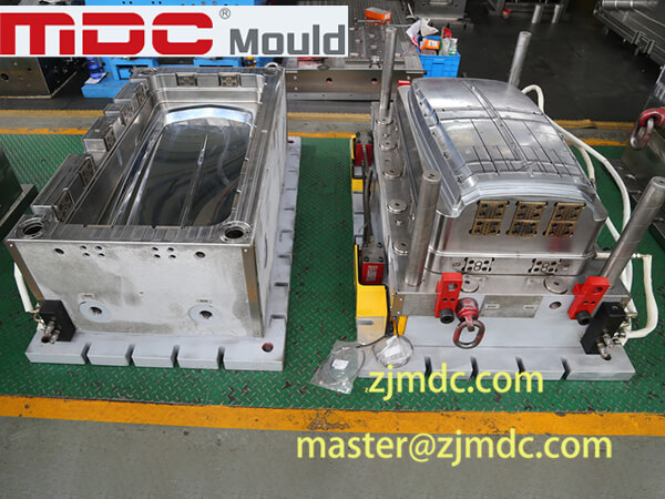
How Chrome Plating and Surface Engineering Extend SMC Mold Life
Among all mold protection technologies, surface engineering remains one of the most effective methods for extending tooling life.
Hard chrome plating creates an extremely wear-resistant surface capable of withstanding continuous exposure to abrasive glass fibers and repeated molding cycles.
When combined with precision polishing, surface treatment provides multiple advantages:
- Higher surface hardness
- Improved release performance
- Reduced fiber scouring wear
- Lower maintenance frequency
- Enhanced corrosion resistance
- Improved Class A surface quality
For automotive exterior panels and high-volume industrial applications, properly executed chrome plating often represents one of the most valuable investments in long-term mold durability.

How Preventive Maintenance Extends Tool Life
Even the most advanced mold engineering cannot eliminate the need for preventive maintenance.
Rather than waiting for quality issues to appear, successful manufacturers implement proactive maintenance schedules that include:
- Cavity surface inspection
- Venting system cleaning
- Guide system verification
- Wear plate inspection
- Heating system evaluation
- Periodic polishing and repair
Preventive maintenance significantly reduces unexpected downtime and helps maintain consistent part quality throughout the mold’s service life.
What Determines Whether an SMC Mold Lasts 100,000 or 1,000,000 Cycles?
The difference between a mold that requires major refurbishment after 100,000 cycles and one that successfully exceeds 1,000,000 cycles rarely comes down to a single factor.
Long-term tooling durability is determined by the combined influence of:
- Glass fiber abrasion resistance
- Thermal fatigue management
- Shear edge protection
- Venting performance
- Surface engineering quality
- Structural rigidity
- Preventive maintenance practices
When these factors are addressed during the design and manufacturing stages, tooling can achieve significantly longer service life while maintaining production efficiency and part quality.
MDC’s Approach to Long-Life SMC Mold Engineering
As a professional SMC mold manufacturer, MDC focuses on engineering solutions that maximize mold durability and production stability.
Our development process integrates:
- DFM analysis
- Material flow simulation
- Thermal analysis
- Structural rigidity evaluation
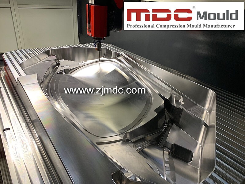
- High-speed CNC machining
- Precision polishing
- Hard chrome plating
- Comprehensive mold testing
By combining advanced engineering with strict manufacturing standards, MDC helps customers achieve longer tool life, lower maintenance costs, and more reliable composite part production.
Conclusion
Premature mold failure is rarely the result of a single defect. Instead, it develops through the combined effects of abrasion, thermal fatigue, alignment issues, venting deterioration, and insufficient surface protection.
Manufacturers that understand these failure mechanisms can make better tooling decisions and significantly improve the lifetime value of their investments. For demanding automotive, EV, infrastructure, and industrial applications, advanced SMC mold engineering remains the foundation of long-term manufacturing success.