Can Fiberglass Products Cause Skin Irritation or Injury?

Learn whether fiberglass products can cause skin irritation or injury. Explore the science of fiberglass composites, health effects, safe handling practices, and industry applications.

Fiberglass, also known as glass fiber, is a critical material in composite manufacturing. This article explores whether fiberglass products can harm people, potential health risks, and best practices for safe handling.

What Is Fiberglass?

Fiberglass is produced by drawing molten glass into thin filaments (typically 5–25 micrometers in diameter). These filaments are woven, chopped, or combined with resin to create fiber-reinforced composites (FRP). Thanks to its lightweight, high strength, corrosion resistance, and affordability, fiberglass is widely used across industries.

Common Applications

  • Construction: insulation, roofing, pipes, and water tanks.
  • Transportation: boats, car panels, truck fairings.
  • Energy: wind turbine blades, pipelines, storage vessels.
  • Consumer Goods: sports gear, helmets, ladders, storage boxes.
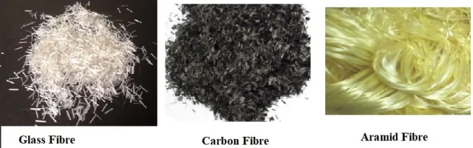
fiber

Can Fiberglass Products Cause Injury?

Fiberglass is not as dangerous as many believe, but exposure can cause temporary discomfort. Key health effects include:

1. Skin Irritation

Fiberglass filaments are brittle and can break into microscopic fragments that may lodge in the outer skin layer. This can cause itching, redness, or prickling, but usually does not result in deep punctures.

2. Respiratory Irritation

Machining processes (cutting, sanding) can release airborne fibers. Larger fibers cause throat irritation, while smaller respirable fibers may lead to coughing. Modern fiberglass types like E-glass and S-glass are classified as non-carcinogenic.

3. Eye and Mucous Membrane Discomfort

Dust exposure can irritate the eyes, leading to burning, tearing, or redness. Contact lenses may worsen the discomfort.

4. Long-Term Health Risks

Unlike asbestos, fiberglass is biosoluble, meaning fibers gradually dissolve and leave the body. Research shows that long-term occupational exposure does not significantly increase cancer risks if safety standards are followed.

Factors Affecting Safety

  • Surface Finish: Smooth, resin-coated products are safe to handle, while raw mats and chopped strands may shed fibers.
  • Fiber Size: Small fractured fibers (<10 μm) cause most irritation.
  • Work Environment: Poor ventilation during cutting or sanding increases risk.

Best Practices for Safe Handling of Fiberglass

  • Personal Protective Equipment (PPE): Gloves, long sleeves, goggles, and respirators.
  • Engineering Controls: Use dust extraction and wet cutting techniques.
  • Hygiene: Wash skin with cold water first, then soap; avoid rubbing. Wash work clothes separately.
  • Product Design: Use sealed, coated, or resin-rich composites to reduce fiber release.

Myths vs. Reality

  • Myth: Fiberglass splinters stab the skin like glass shards.
    Reality: Fibers are flexible and brittle, causing surface irritation rather than deep wounds.
  • Myth: Fiberglass is as hazardous as asbestos.
    Reality: Fiberglass dissolves in lung fluids and is not classified as carcinogenic when proper handling is observed.

Future Development Trends

  • Smart composites: Embedded sensors for real-time monitoring.
  • Eco-friendly solutions: Recyclable fiberglass composites with green resins.
  • Hybrid materials: Combining fiberglass with carbon, basalt, or natural fibers.
  • Automation: Robotic handling to reduce worker exposure.

Conclusion

Fiberglass products are safe for industrial and consumer use when manufactured and handled correctly. While raw or machined fiberglass may cause temporary irritation, finished products are typically harmless. With proper PPE, ventilation, and hygiene, risks can be minimized.

As composite technology advances, fiberglass will remain one of the most versatile, safe, and sustainable materials across industries—from construction and energy to transportation and consumer goods.

Frequently Asked Questions (FAQ)

Does fiberglass cause permanent damage to skin?

No. Fiberglass fibers cause temporary irritation but rarely penetrate deep enough to cause lasting harm.

Is fiberglass dust dangerous to inhale?

Short-term exposure causes irritation, but modern fiberglass is biosoluble and does not persist like asbestos. Always use protective masks when cutting or sanding.

Are finished fiberglass products safe to touch?

Yes. Resin-coated and polished fiberglass composites are safe for everyday handling and use.

Composite Materials in Hydropower Dam Construction: Applications & Benefits

Explore how advanced composite materials like GFRP, CFRP, and BFRP are revolutionizing hydropower dam construction. Learn about their applications in structural reinforcement, erosion control, and more.

The construction of large-scale hydropower stations represents a monumental engineering challenge. These projects demand materials that can withstand extreme forces, constant exposure to water, and harsh environmental conditions. While traditional materials like steel and concrete have long been the backbone of these projects, the integration of advanced composite materials has introduced a new era of innovation, offering superior performance in specific applications.

With their high strength-to-weight ratio, exceptional corrosion and fatigue resistance, and remarkable design flexibility, composites are increasingly supplementing or even replacing conventional materials in critical components. This article provides a comprehensive overview of the most common composite materials used in hydropower dam construction, detailing their unique properties and key applications, from structural reinforcement to erosion protection.

Glass Fiber Reinforced Polymer (GFRP): Versatile & Cost-Effective

GFRP, often referred to as fiberglass, is one of the most widely used composite materials in hydro-engineering due to its favorable cost-to-performance ratio. Its excellent corrosion resistance, low weight, and insulating properties make it an ideal choice for a variety of non-primary structural components and protective systems.

  • Pressure Pipes & Penstock Linings: GFRP pipes are an excellent alternative to traditional steel pipes, particularly for small to medium diameters. They are lightweight, making installation easier, and their smooth inner surface reduces friction, improving hydraulic efficiency.
  • Accessways, Walkways, & Grates: GFRP gratings and floor panels are widely used in maintenance corridors and walkways. They are lightweight, non-corrosive, non-conductive, and offer superior slip resistance, making them perfect for the perpetually wet environments of hydropower facilities.
  • Cable Trays & Conduits: The excellent electrical insulation and corrosion resistance of GFRP make it the material of choice for cable trays and protective conduits, ensuring the safety and longevity of electrical systems.
  • Trash Racks: Replacing metal bars in trash racks with GFRP can significantly reduce weight and minimize the maintenance associated with rust and corrosion.

Carbon Fiber Reinforced Polymer (CFRP): The Gold Standard for Structural Reinforcement

CFRP is a high-performance composite known for its extremely high specific strength and stiffness. Its primary application in hydropower is in the structural strengthening and repair of aging infrastructure.

  • Dam & Structure Reinforcement: CFRP is a game-changer for extending the service life of concrete structures. Carbon fiber sheets or plates can be bonded to dams (gravity dams, arch dams), powerhouse structures, spillway piers, and tunnel linings to enhance their load-bearing capacity and repair cracks.
  • High-Performance Components: In high-head, high-speed turbines, CFRP can be used to manufacture or repair critical areas of turbine blades, offering exceptional strength and rigidity while reducing weight.
  • Sensor Encapsulation: CFRP is used to encapsulate and protect sensitive sensors, such as fiber Bragg grating sensors, that are embedded within concrete structures for long-term monitoring.

Aramid Fiber Reinforced Polymer (AFRP): Engineered for Impact & Protection

AFRP, a composite made from aramid fibers like Kevlar, is valued for its extraordinary toughness and impact resistance. Its role is crucial for safety and protection, particularly in manufacturing protective panels.

  • Protective Armor Panels: The primary use of AFRP is in manufacturing protective panels to shield critical equipment and personnel from flying debris, such as in generator halls or control rooms.

Ultra-High Molecular Weight Polyethylene (UHMWPE) Composites: The Ultimate in Abrasion Resistance

UHMWPE is a unique material with a remarkably low coefficient of friction and exceptional resistance to abrasion, making it indispensable in areas of hydropower stations subjected to high-velocity, sediment-laden water.

  • Abrasion-Resistant Linings: UHMWPE liners are installed in draft tubes, spillways, and sluiceways where sediment scour is a major issue. Its abrasion resistance is several times greater than that of steel.
  • Bearings & Slides: Its self-lubricating properties and wear resistance make UHMWPE an excellent material for gate slides and other mechanical components that require low-friction bearings.

Basalt Fiber Reinforced Polymer (BFRP): A Promising, Sustainable Alternative

BFRP is emerging as a strong contender in the composite market, offering properties that bridge the gap between GFRP and CFRP. Made from a widely available natural resource, basalt rock, it presents a more sustainable and often more cost-effective option.

  • Reinforcement Bars (BFRP Rebar): BFRP rebar is an ideal substitute for steel rebar in concrete structures exposed to corrosive environments, completely eliminating the risk of rebar corrosion.

Engineering Ceramic Composites & Coatings: The Front Line of Erosion Protection

Cavitation and abrasion are two of the most destructive forces acting on turbine components. Ceramic matrix composites and ceramic coatings provide an extremely hard and durable surface to combat this wear.

  • Anti-Erosion & Anti-Cavitation Coatings: These coatings are crucial for protecting turbine runner blades, wicket gates, and spillway floors. Common materials include tungsten carbide (WC) and chromium carbide (Cr₃C₂).
Hydropower Dam

Summary & Future Trends in Hydro-Engineering

The application of composite materials in hydropower is a testament to the industry’s commitment to durability, efficiency, and long-term sustainability. The strategic use of materials like GFRP for non-structural parts, CFRP for critical structural repairs, and UHMWPE for high-wear areas ensures the longevity and resilience of these massive projects.

As composite technology continues to advance and costs decrease, their role in the construction, maintenance, and operation of hydropower stations will only become more extensive. The introduction of these materials, as exemplified in projects like the Yarlung Tsangpo Hydropower Station‌, underscores a forward-thinking approach to building the next generation of resilient and efficient energy infrastructure.

Precision Cooling Fixtures and 3D Scanning Inspection

Explore how MDC Mould combines custom-designed cooling fixtures and high-precision 3D scanning inspection to ensure dimensional stability in molded SMC parts.

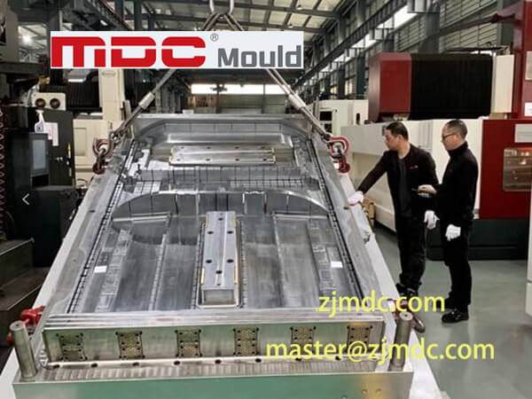
In modern composite molding—particularly in SMC (Sheet Molding Compound) and BMC (Bulk Molding Compound) processes—dimensional accuracy, repeatability, and post-molding stability are fundamental. As a leading mold manufacturer, MDC Mould is continuously optimizing not just the tooling, but the entire downstream validation process. This article introduces our latest innovation: a custom cooling fixture engineered in-house and integrated with advanced 3D scanning inspection to guarantee consistent and reliable dimensional control.

Why Dimensional Stability Matters in Composite Molding

Composite materials like SMC and BMC are known for their excellent strength-to-weight ratio, corrosion resistance, and design flexibility. However, they are also prone to thermal shrinkage and post-molding deformation due to temperature differentials, uneven pressure, or uncontrolled cooling. Without a strategy to simulate real-use cooling conditions, even a precisely molded part may fall outside tolerance during the cooling phase.

To mitigate this, MDC Mould has developed a process that combines custom part-specific cooling fixtures with non-contact 3D metrology, bridging the gap between mold fabrication and functional performance verification.

Our Custom Cooling Fixture: Designed for Functionality and Accuracy

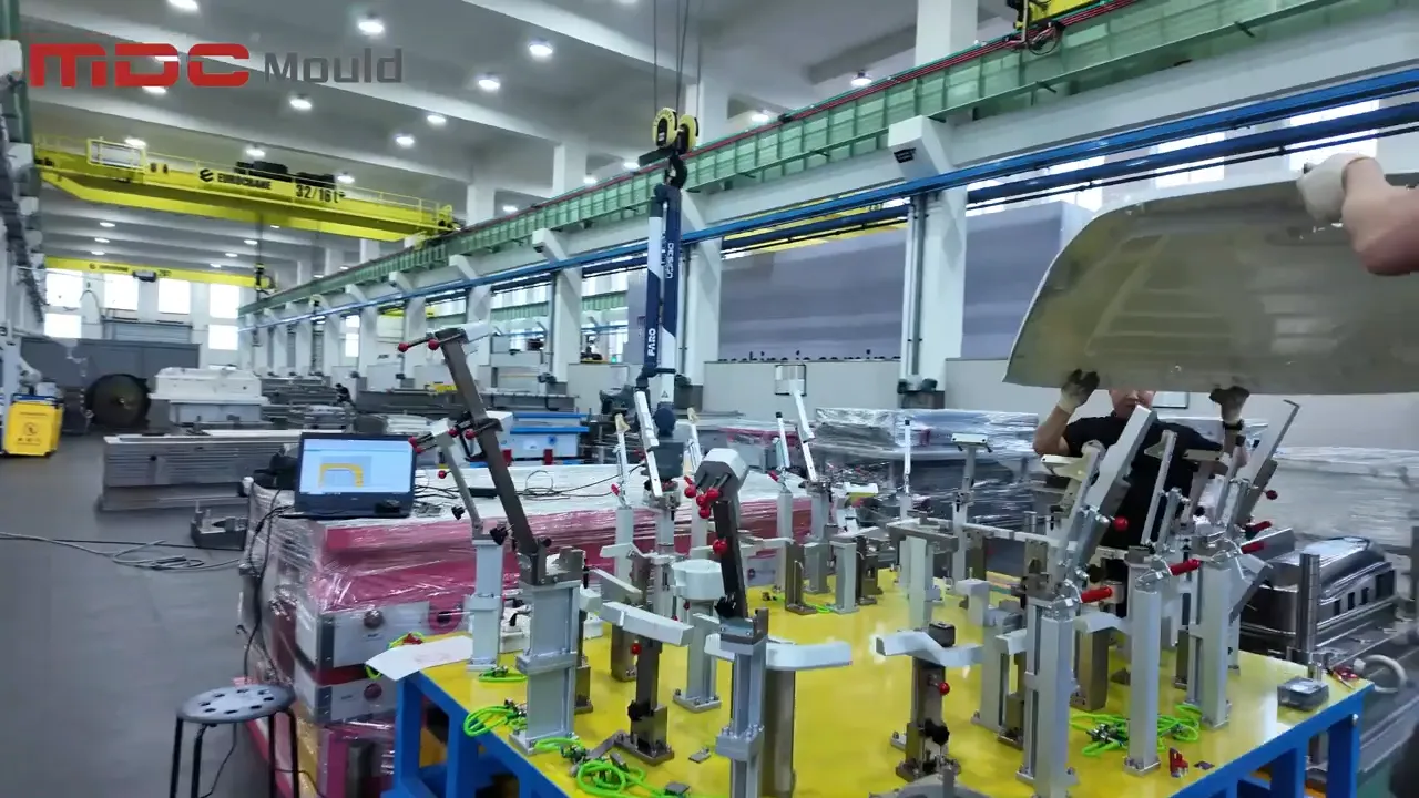
The cooling fixture is more than just a supporting frame—it is a precision-engineered device tailored to the exact geometry of the molded part. Here’s how it works:

  • Shape Conformance: The fixture mirrors the molded part’s final geometry, ensuring uniform cooling without stress points or sagging.
  • Post-Molding Simulation: By simulating how the part would cool in real use, we prevent unrealistic deformation during measurement.
  • Stabilization During Scanning: The fixture holds the part in position to enable reliable and repeatable 3D inspection.
  • Material-Specific Tuning: Each fixture is designed with the thermal behavior of the composite material in mind.

Fixtures are custom-built in our tool shop using CAD/CAM systems, ensuring high fitting accuracy and repeatability. This integration of engineering design with quality inspection reflects our deep understanding of mold-formed component behavior.

Precision Fixtures

Advanced 3D Scanning Inspection for High-Resolution Feedback

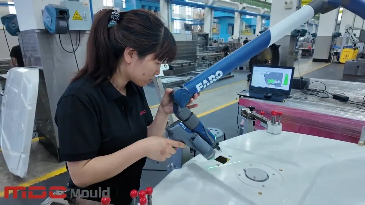
Once the part is fully cooled and stabilized, it is scanned using state-of-the-art 3D scanning equipment that generates detailed point cloud data. We then:

  • Align the scan data with the original CAD model
  • Run full 3D dimensional analysis with deviation mapping
  • Generate a complete 3D inspection report with color-coded tolerances
  • Deliver this report to the customer for transparent feedback and sign-off

This non-contact inspection process is faster, more accurate, and more comprehensive than traditional CMM-based techniques, especially for freeform or large-area parts.

Integrated Quality Assurance: Closing the Loop

Our combined use of cooling fixtures and 3D scanning inspection offers an end-to-end solution for dimensional control. This method ensures that the molded part conforms not only to its designed geometry, but also to its functional form after cooling—the true test of manufacturing success.

Benefits at a Glance:

  • Reduced rejection rates through early detection of dimensional drift
  • Repeatable QA procedures that can be benchmarked and scaled
  • Enhanced customer trust through full transparency of inspection data
  • Faster iterations for pilot runs and new product development
3D Scanning Inspection

Applications Across Industries

This solution is particularly suited to industries where geometric precision and thermal stability are critical, including:

  • Automotive: Battery covers, inner roof panels, trunk boards, engine splash shields
  • Electrical: Enclosures and insulators made from BMC/SMC
  • Infrastructure: GRP water tank components with large surface areas
  • Aerospace: Lightweight structural panels requiring strict tolerance control

Why Choose MDC Mould?

We’re more than a mold supplier—we are a comprehensive partner in precision manufacturing. From mold design and tool fabrication to post-molding inspection and process optimization, MDC Mould provides a complete solution rooted in engineering excellence.

With a focus on composite mold development—including SMC molds, BMC molds, carbon fiber tooling, and compression molds—we understand the challenges and requirements of your applications.

Let’s Engineer Success Together

If your project demands tight tolerances, high repeatability, and confidence in quality assurance, MDC Mould is your trusted partner. Contact us today to learn how our cooling fixtures and 3D inspection workflows can add value to your production line.

Composite Molding Exterior: High-Performance Solutions

Discover the advantages, applications, and technologies behind composite molding exterior parts for automotive, architecture, and industrial uses.

Composite molding exterior refers to the manufacturing of durable, lightweight, and aesthetically advanced exterior parts using compression molding technologies. These components are made from high-strength materials such as SMC (Sheet Molding Compound), BMC (Bulk Molding Compound), and carbon fiber-reinforced polymers. They are widely used in the automotive industry, architectural panels, commercial transportation, and outdoor infrastructure.

Why Choose Composite Molding for Exterior Applications?

Composite molding offers superior performance over traditional materials such as metal and plastic in demanding exterior environments. Key advantages include:

  • Weather Resistance: Excellent durability against UV, rain, heat, and frost.
  • Lightweight & Strong: Ideal for reducing structural load while maintaining strength.
  • Design Flexibility: Molds allow for complex shapes, textures, and surface finishes.
  • Corrosion-Free: Unlike metals, composites do not rust or corrode.
  • Sustainability: Recyclable materials and energy-efficient production processes.
front panel mould

Core Composite Molding Technologies

SMC Molding

SMC is a fiberglass-reinforced polyester material widely used for large-scale exterior parts. Common SMC exterior molds include automotive bumper molds, truck exterior panel molds, and antenna cover molds. It supports high-volume production with excellent repeatability and precision.

BMC Molding

BMC offers excellent dielectric properties, making it suitable for electrical enclosures and junction box covers exposed to outdoor conditions. BMC molds ensure tight tolerances and reliable structural integrity.

Carbon Fiber Molding

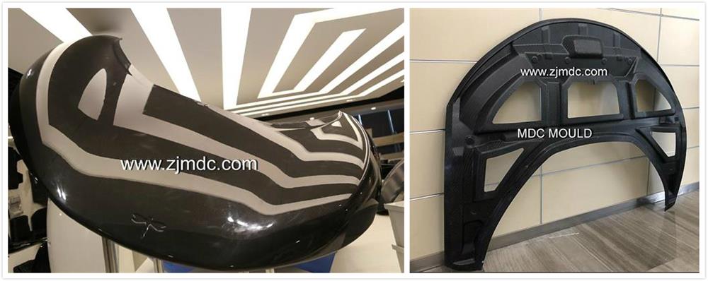
Carbon fiber molding is applied to high-performance sectors such as motorsports and aerospace. For exterior use, it provides unmatched strength-to-weight ratio and a sleek appearance, commonly used in racing car body kits, mirror housings, and hoods.

Typical Applications

  • Automotive: Bumper covers, tailgates, side skirts, mirror covers, wheel arches
  • Commercial Vehicles: Truck fairings, rear guards, cab exteriors
  • Architecture: Decorative façade panels, soffits, eaves, outdoor signage
  • Infrastructure: Antenna housings, distribution box covers, smart city terminals
carbon fiber part

Precision Molds for Composite Exterior Parts

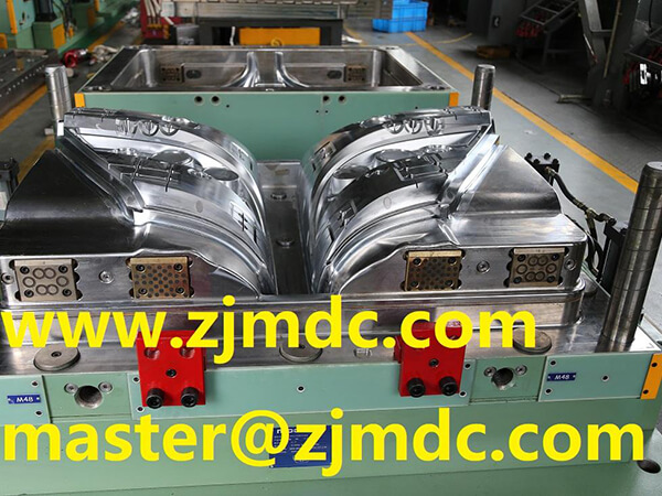
High-quality molds are crucial to the success of composite exterior molding. At MDC Mould, we provide expert tooling for:

  • SMC bumper molds
  • SMC truck panel molds
  • Carbon fiber car body molds
  • Composite antenna housing molds
  • BMC distribution box molds

Conclusion

Composite molding exterior solutions are revolutionizing the way exterior components are produced and used across industries. Their performance, versatility, and sustainability make them a smart choice for next-generation design and manufacturing.

Whether you need custom SMC exterior molds, carbon fiber tooling, or composite molding solutions, we’re here to help you turn your concept into high-precision products.

What are the Characteristics of Compression Molding Molds?

Learn about the key characteristics of compression molding molds, including precision, durability, material selection, and industry applications for optimized production.

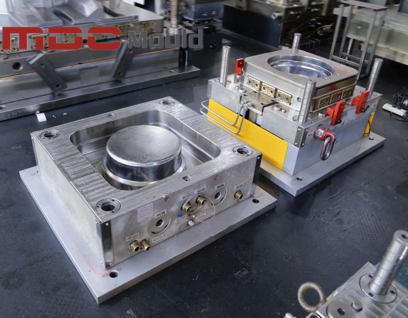
Compression molding is a high-efficiency, cost-effective method for producing complex parts using composite materials. The molds used in this process—known as compression molds—are essential in ensuring quality, strength, and durability of the finished product. This article explores the main characteristics of compression molding molds, including their structure, materials, applications, and unique advantages.

1. Precision and Customization in Mold Design

Compression molding molds offer customization for various applications, such as automotive and industrial panels. They support:

  • Custom Part Geometry: Tailored molds for complex shapes.
  • Tolerance Control: Ensures precise part dimensions and reduces material waste.
3d mould

2. Materials for Compression Molding Molds

Compression molds are usually made from robust materials capable of withstanding high pressures and temperatures:

  • Steel: Ideal for high-cycle durability.
  • Aluminum: Great for lower-volume runs due to its thermal conductivity.
  • Beryllium Copper: Used for intricate details and high thermal conductivity.

3. Mold Structure and Key Components

Key structural elements of compression molding molds include:

  • Cavity and Core: Define the product shape.
  • Heating System: Ensures material curing.
  • Ejector System: Facilitates part release.
  • Guiding System: Aligns mold halves for accuracy.
bottom cover mould

4. High Heat Resistance and Stability

Compression molds must withstand high temperatures for material curing, with features such as:

  • Heat Resistance: Withstands up to 300°F or higher.
  • Dimensional Stability: Retains shape under high temperatures and pressure.
  • Even Heat Distribution: Reduces cycle times and ensures quality.

5. Durability and Longevity

Compression molds are designed for durability, often lasting thousands of cycles:

  • Material Choice: High-quality steel and alloys enhance longevity.
  • Surface Treatment: Chrome plating for wear resistance.
  • Cycle Efficiency: Reduced wear compared to other mold types.

6. Cycle Time Efficiency

Efficient cycle times are essential for compression molding. Factors enhancing efficiency include:

  • Quick Heat Transfer: High thermal conductivity materials reduce heating time.
  • Optimized Part Release: Smooth finishes and ejector mechanisms minimize sticking.
SMC (sheet molding compound)

7. Compatibility with Composite Materials

Compression molds are compatible with a variety of composite materials like SMC, BMC, and thermosets:

  • Material Flow: Even distribution for defect-free parts.
  • Material Curing: Even curing for strength and durability.

8. Applications Across Diverse Industries

Compression molds are widely used in industries including automotive, aerospace, and electrical:

  • Automotive: Panels, body parts, and interior components.
  • Electrical: Insulators and housings with precise tolerances.
  • Household Products: Durable components for daily use.

9. Cost-Effectiveness and Efficiency

Compression molding offers a cost-effective solution for medium to high-volume production:

  • Low Material Waste: Pre-measured charges minimize excess material.
  • Low Tooling Costs: Compared to injection molding.
  • Simplified Setup: Reduces operational costs.
insp

10. Design Flexibility and Enhanced Surface Finish

Compression molding molds offer flexibility and high-quality finishes:

  • Texture and Pattern Integration: Custom finishes for aesthetic appeal.
  • High-Quality Surface Finish: Smooth results, reducing post-processing needs.
  • Minimal Draft Angles: More precise part geometries.

Conclusion

The characteristics of compression molding molds—durability, precision, and compatibility with composite materials—make them essential for high-quality production in diverse industries. These qualities not only ensure product durability but also optimize production efficiency. By understanding these characteristics, manufacturers can make informed decisions, improving product outcomes and achieving cost-effective, reliable manufacturing solutions.

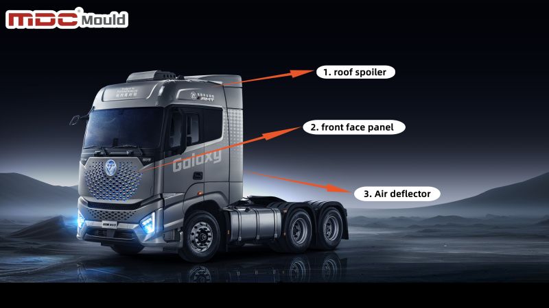
Auman Galaxy Truck: Powered by Innovative SMC Molds from MDC Mould

Explore how Zhejiang MDC Mould Co., Ltd. developed innovative SMC molds for Foton Daimler's Auman Galaxy truck, including SMC roof spoiler molds, SMC front face panel molds, and SMC air deflector molds.

The release of the Auman Galaxy truck by Foton Daimler marks a groundbreaking moment in the commercial vehicle industry, blending sleek design with optimal performance. Integral to this innovation is the advanced SMC mold technology provided by Zhejiang MDC Mould Co., Ltd., responsible for manufacturing crucial structural components of the truck.

SMC Molds: Turning Vision into Reality

MDC Mould worked tirelessly to bring this project to life. From the concept stage to serial production, the company created state-of-the-art SMC molds including molds for the SMC roof spoiler, SMC front face panel, and SMC air deflector. In just 12 weeks, MDC Mould transformed these components from prototypes to high-quality serial tools.

This achievement not only reflects MDC’s technical expertise but also highlights their commitment to meeting demanding deadlines without compromising quality.

smc mold Auman Galaxy Truck

Understanding SMC Materials in Automotive Manufacturing

Sheet Molding Compound (SMC) is a composite material made from thermosetting resins, glass fibers, and other additives, and is widely used in automotive manufacturing. Its combination of strength, durability, and lightweight properties makes it ideal for vehicle parts that require high performance while reducing weight.

For the Auman Galaxy truck, MDC Mould’s SMC molds were essential in creating parts such as the roof spoiler, front face panel, and air deflector, improving aerodynamics and enhancing the vehicle’s overall efficiency.

Advantages of SMC in Automotive Components

SMC offers several key advantages in the automotive sector:

  • Lightweight: Reduces the overall weight of vehicles, leading to improved fuel efficiency and reduced emissions, which is especially important for electric vehicles like the Auman Galaxy.
  • High Strength: Despite being lightweight, SMC components offer excellent structural integrity, capable of withstanding harsh environmental conditions and mechanical stress.
  • Corrosion Resistance: SMC parts are highly resistant to corrosion, making them ideal for exterior automotive components exposed to the elements.
  • Cost-Effective: SMC’s efficiency in the molding process reduces manufacturing costs while maintaining high product quality.
automotive air conditioner cover mould

Detailed Overview of SMC Molds for the Auman Galaxy Truck

1. SMC Roof Spoiler Mold

The SMC roof spoiler mold provided by MDC Mould was designed with precision, ensuring optimal aerodynamics and a perfect fit. The roof spoiler not only enhances the truck’s sleek appearance but also contributes to improved fuel efficiency by reducing drag.

2. SMC Front Face Panel Mold

The SMC front face panel mold adds a distinctive touch to the truck’s exterior. This component offers both style and function, giving the vehicle a strong front-end appearance while maintaining durability and impact resistance.

3. SMC Air Deflector Mold

The SMC air deflector mold is another critical component manufactured by MDC Mould. It helps in directing airflow smoothly around the truck, reducing air resistance and noise, thereby contributing to a more fuel-efficient and quieter ride.

Rapid Tooling for Urgent Projects

From prototype to serial tool production, MDC Mould completed the development of these molds in just 12 weeks. Their rapid tooling capabilities make them an ideal partner for projects with urgent lead times. This speed doesn’t come at the expense of quality; MDC Mould employs cutting-edge technology to ensure every mold meets strict industry standards.

compression mold

MDC Mould’s Commitment to Quality and Innovation

With years of experience in the automotive mold industry, MDC Mould is a trusted partner for companies looking for high-quality, reliable molds. Their expertise spans across various sectors, including electric vehicles, making them a leader in the development of SMC molds for the next generation of trucks and cars.

MDC Mould’s team is always ready to take on new challenges, providing tailored solutions for every project. Whether you need SMC molds, compression molds, or other composite mold solutions, MDC Mould is equipped to meet your needs with precision and efficiency.

Partner with MDC Mould for Your Next Project

If your project has a tight timeline or specific technical requirements, reach out to MDC Mould for innovative solutions. Their team is committed to delivering high-quality molds on time, ensuring that your production stays on track.

How Long Does Compression Molding Take? | Compression Molding Process & Cycle Time?

Learn how long compression molding takes, the factors affecting cycle times, and how to optimize compression molding processes for efficiency.

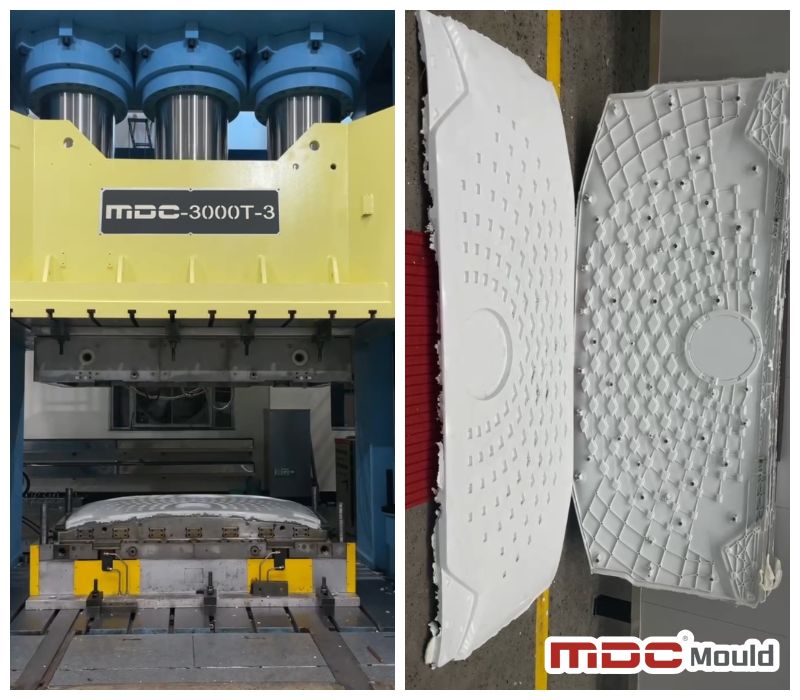
Compression molding is a widely used manufacturing process for producing high-strength components from composite materials, thermoplastics, and thermoset plastics. The time it takes to complete one molding cycle—known as the cycle time—varies depending on several key factors. In this article, we will explore what influences compression molding time and how long it typically takes to complete a compression molding process.

Factors That Affect Compression Molding Time

Several factors can affect the length of a compression molding cycle. Below are the most important considerations:

  • Material Type: Thermoset materials like SMC (Sheet Molding Compound) and BMC (Bulk Molding Compound) usually take longer because they require curing. Thermoplastics generally have shorter molding times because they do not need curing.
  • Mold Design: Complex mold designs with intricate shapes take more time to fill and cure. Efficient mold design can minimize cycle time.
  • Part Thickness: Thicker parts require longer time for heat to penetrate evenly, resulting in longer cycle times.
  • Temperature: Higher mold temperatures can reduce curing or melting times, but excessive heat may cause defects.
  • Curing Time: Curing ensures that thermoset materials harden properly. The required curing time can range from minutes to over 30 minutes, depending on the material and part size.
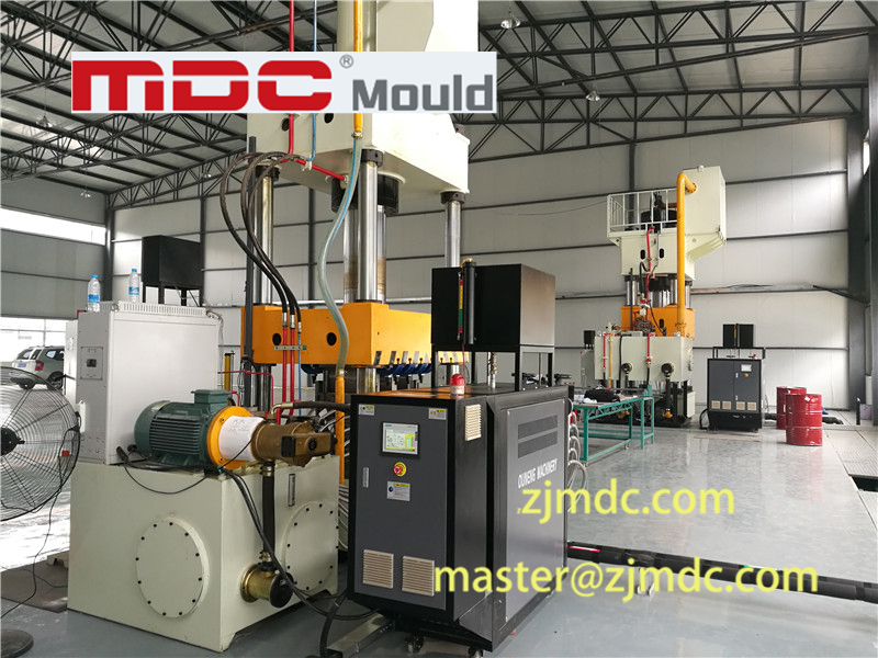
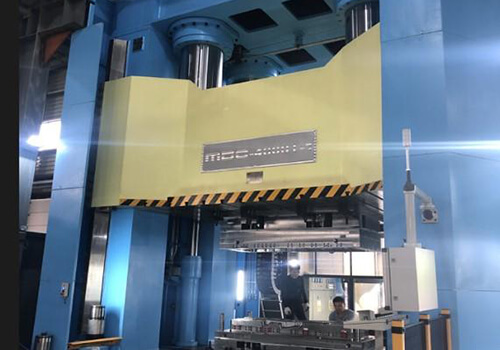
compression molding machine
compression mould machine

Typical Compression Molding Cycle Time

The cycle time for compression molding typically ranges from 1 to 10 minutes, but it can be longer for complex parts or larger components. The specific time depends on the material, mold design, and part size:

  • Simple Parts: Thin, uncomplicated parts made from thermoplastic materials may have a cycle time of 30 seconds to 2 minutes.
  • Complex Parts: For parts made from thermoset materials like SMC or BMC, the cycle time is usually between 5 to 10 minutes.
  • Thicker Parts: Larger or thicker parts requiring more material and time to cure may extend the cycle time beyond 10 minutes.

For high-volume production environments, such as in automotive or aerospace component manufacturing, optimizing cycle time is crucial for efficiency. Manufacturers constantly aim to reduce cycle time without compromising product quality.

compression-molding

Compression Molding Process Breakdown

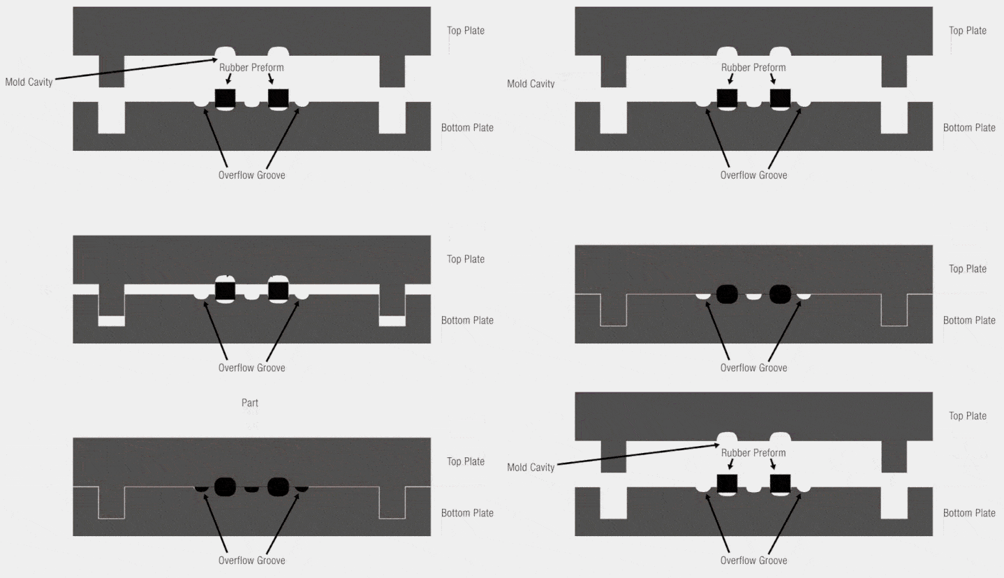
Here’s a breakdown of the typical stages of the compression molding process and their respective timeframes:

  • Preheating (Optional): Preheating the material can reduce cycle time and takes around 1 to 3 minutes.
  • Material Loading: The material is placed into the mold, which usually takes 30 seconds to 1 minute.
  • Mold Closing and Pressing: The mold is closed, and heat and pressure are applied, lasting 30 seconds to 10 minutes.
  • Curing Time: This step is crucial for thermoset materials, with times ranging from 2 to 15 minutes.
  • Cooling (Optional): Some thermoplastic parts may require a cooling phase, lasting 1 to 3 minutes.
  • Part Ejection: Once the part is cured or cooled, it is ejected from the mold, taking 10 to 30 seconds.

Strategies for Reducing Compression Molding Time

There are several ways to reduce cycle time in compression molding without sacrificing quality:

  • Optimize Material Flow: Improving material flow can ensure faster filling of the mold cavity.
  • Preheating: Preheating the material before molding reduces pressing and curing times.
  • Automation: Automated loading and ejection systems can streamline the process.
  • Multi-Cavity Molds: Using molds with multiple cavities allows multiple parts to be produced simultaneously.
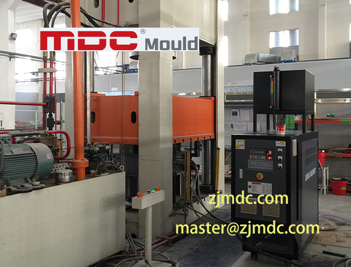
  • Optimize Mold Temperature: Advanced temperature control systems can maintain optimal mold temperatures to reduce cycle time.
compression tooling

Conclusion

Compression molding time can vary significantly based on factors like material type, part thickness, mold design, and temperature. The cycle time typically ranges from 1 to 10 minutes, but larger or more complex parts may require more time. Manufacturers who optimize key aspects of the process, such as curing time, material flow, and automation, can significantly reduce cycle times and improve production efficiency.

Understanding how long compression molding takes is essential for managing production schedules and meeting delivery timelines, especially in industries like automotive, aerospace, and consumer goods.

Carbon Fiber and Composite Materials: A New Era for Heavy-Load Railway Freight Cars

Discover the advancements in carbon fiber composite materials and compression molding technology that revolutionize heavy-load railway freight cars.

The Role of Carbon Fiber Composite Materials in Modern Rail Transportation

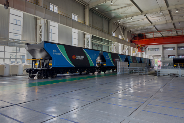
On September 10, 2024, the first batch of six carbon fiber composite heavy-load railway freight cars rolled off the production line, showcasing cutting-edge lightweight and smart designs. This significant milestone marks a breakthrough in the use of carbon fiber composite materials for heavy-load railway mobile equipment.

carbon fiber composite railway

Jointly developed by the China Energy Group’s Railway Equipment Company, the Beijing Low-Carbon Clean Energy Research Institute, and CRRC Qiqihar Rolling Stock Co., Ltd., these railway freight cars not only represent a leap forward in the application of new materials but also contribute to green, low-carbon rail transportation solutions.

Lightweight and Intelligent Design for Energy Efficiency

Under the guidance of national strategies like “Strengthening Transportation” and “Dual Carbon,” there is a growing demand for the green transformation of the transportation sector. The China Energy Group, managing over 57,000 railway freight cars, plays a key role in transitioning toward energy-efficient, lightweight solutions for large-scale freight operations, particularly in coal transport.

The new carbon fiber composite railway freight cars are a significant advancement in lightweight, high-strength, and low-energy solutions. These cars are a direct result of integrating compression molding technology and advanced composite materials, setting new benchmarks for efficiency and sustainability.

Advantages of Carbon Fiber Composite Materials

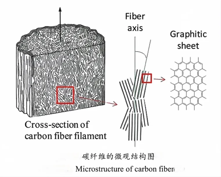
1. Higher Strength-to-Weight Ratio

Compared to traditional materials, carbon fiber composites offer a strength-to-weight ratio 3-5 times higher than aluminum alloys, making them ideal for heavy-load railway freight cars. This higher ratio allows for reduced vehicle weight without compromising structural integrity.

2. Reduced Weight for Increased Efficiency

The carbon fiber composite body reduces the weight of the railway freight cars by more than 20% compared to similar aluminum vehicles. This significant weight reduction, with a self-weight coefficient as low as 0.22, allows for greater load capacity and improves overall transportation efficiency.

3. Enhanced Durability and Environmental Resistance

Carbon fiber composites also exhibit superior resistance to harsh environmental conditions, making these materials more durable than traditional metals. This durability is essential for long-term operation and minimal maintenance, ensuring that these railway freight cars can withstand extreme conditions over their lifespan.

microstructure of carbon fiber

Technological Innovations in Heavy-Load Freight Cars

1. Optimized Bogies and Air Brake Systems

The new cars are equipped with optimized K6-type bogies, which enhance load distribution and stability. Integrated air brake systems ensure efficient braking, further improving the cars’ safety and control.

2. Smart Monitoring Systems for Real-Time Data Collection

These freight cars incorporate smart monitoring systems powered by IoT, big data, and cloud computing, enabling real-time data collection on the performance of the cars. This system improves predictive maintenance and helps optimize energy consumption, contributing to greener transportation solutions.

Compression Molding: A Key Manufacturing Technique

The use of compression molding for carbon fiber composite materials has been instrumental in the development of these new railway freight cars. Compression molding allows for the efficient production of large, complex parts with precision, making it ideal for large-scale components such as the car bodies.

Advantages of Compression Molding for Carbon Fiber Components

  • High precision and consistency in part production.
  • Efficient manufacturing of large parts in a single operation.
  • Minimized material waste, especially important with high-cost materials like carbon fiber.
compression mold

Conclusion: Pioneering the Future of Green Rail Transport

The successful development of carbon fiber composite heavy-load railway freight cars signals a major step forward in the future of rail transportation. With the combined benefits of lightweight design, improved durability, and cutting-edge technologies like smart monitoring systems, these cars offer revolutionary advantages for green, low-carbon transport.

As global transportation continues to evolve, the integration of composite materials and compression molding technology will remain pivotal in shaping the next generation of heavy-load railway freight equipment.

Effects of Thermoforming Parameters on Carbon Fiber Thermoplastic Composites

Discover the effects of thermoforming parameters on woven carbon fiber fabric/polycarbonate thermoplastic composites, including optimal values for spring-back angle, mold shape fitness, and key parameters for composite molds.

The quality of woven carbon fiber fabric/polycarbonate thermoplastic composites after thermoforming and demolding has been a subject of considerable research, especially for applications in industries that require SMC molds and composite molding. These composites are critical in sectors utilizing compression molds and carbon fiber molds.

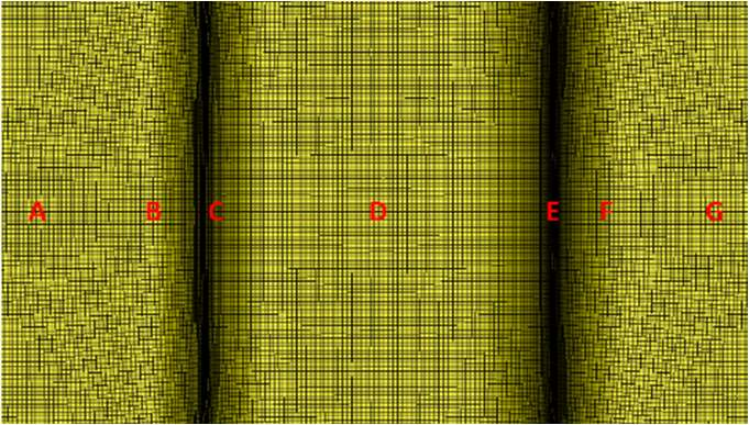
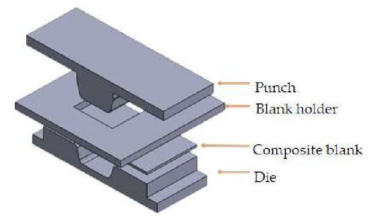
This study investigates the effects of thermoforming parameters using a combination of finite element simulation and the Taguchi orthogonal array. The simulation model employed a discrete approach with a micro-mechanical model to describe the deformation behavior of the woven carbon fiber fabric, similar to what is seen in thermoforming molds and compression tooling. In parallel, a resin model was incorporated to ensure accurate simulations. This approach was validated through bias extension tests conducted at five different temperatures, providing essential data on material behavior during the thermoforming process, much like processes involving BMC molds and press molds.

composite

Key Thermoforming Parameters

The study focused on three key thermoforming parameters, each having three levels, similar to those considered in compression molding:

  • Blank Temperature: Influences the material’s flexibility and ability to conform to mold shapes, crucial in SMC tooling and BMC molding.
  • Mold Temperature: Affects the final shape fitness and surface finish of the composite, often impacting thermoforming molds and SymaLITE molds.
  • Blank Holding Pressure: Plays a crucial role in keeping the material in place and ensuring consistent molding, essential for composite molds like SMC moulds and carbon fiber molds.

The objective was to optimize four important quality factors: fiber-enclosed angle, spring-back angle, mold shape fitness, and the strain of the U-shaped workpiece, similar to those in thermoset molds and LFT molding. By adjusting the thermoforming parameters, the study aimed to achieve the best combination of these factors across various composite tooling methods.

mold

Results and Analysis

The finite element simulation revealed that the stress-displacement curve obtained from bias extension tests closely matched the simulated results. This verified the reliability of the discrete finite element method used in this study, which has parallels with the validation processes for SMC molding and press tooling.

Moreover, the Taguchi orthogonal array analysis identified blank holding pressure as the dominant process parameter, much like in compression molds and BMC tooling. The optimal value for blank holding pressure was found to be 1.18 kPa, making it the most critical factor in the thermoforming process. Blank temperature was the second most influential factor, with an optimal range of 160°C to 230°C. Interestingly, mold temperature had a relatively minor effect on the final composite quality, similar to the behavior observed in GMT molds and D-LFT molds.

Optimal Thermoforming Settings

The study recommended the following optimal settings for the thermoforming of woven carbon fiber fabric/polycarbonate thermoplastic composites:

  • Blank Holding Pressure: 1.18 kPa (critical for compression molds and SMC moulds)
  • Blank Temperature: 230°C (relevant for thermoforming tools and hot compression molds)
  • Mold Temperature: 190°C (beneficial for composite molding and carbon fiber molds)

These settings resulted in the most favorable outcomes for all four quality factors, indicating that careful control of blank holding pressure and temperature is crucial for achieving high-quality composite molds and thermoforming molds.

The-model-of-the-thermoforming-process

Conclusion

In summary, the results of this study provide valuable insights into the effects of thermoforming parameters on woven carbon fiber fabric/polycarbonate thermoplastic composites. The study concluded that blank holding pressure and blank temperature are the two most important factors, with mold temperature playing a secondary role. These findings are essential for those working with composite tooling, thermoforming tools, and compression molds, providing a clear pathway for producing high-quality composites with desirable spring-back angle, fiber-enclosed angle, and mold shape fitness.

Composite Materials and Processes: Unique Materials Requiring Unique Processes

Discover the unique characteristics and processes of composite materials, including SMC mold, BMC tooling, and carbon fiber molding. Learn about their impact on industries like aerospace, automotive, marine, and sports equipment.

Composite materials, including those produced with SMC mold and BMC tooling, have emerged as game-changing solutions across various industries due to their unique properties, such as a high strength-to-weight ratio and anisotropic behavior. These characteristics have led to the increasing popularity and adoption of composites in industries like aerospace, automotive, marine, and sports equipment.

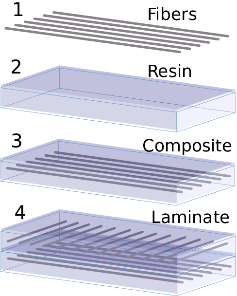
SCHEMATIC PICTURE OF A COMPOSITE LAMINATE

Introduction to Composite Materials and Processes

Composite materials, often crafted using processes such as SMC molding and GMT tooling, offer unique advantages due to their tailored strength and stiffness. These characteristics are achieved through strategic placement and orientation of fibers within the matrix, optimizing the material for specific performance requirements.

Laminate Composites

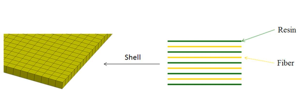
Laminate composites are continuous fiber composites where individual layers are oriented in a manner that enhances strength in the primary load-bearing direction. This method is often employed in SMC moulding and BMC molding to create high-performance components. Essentially, laminates consist of multiple layers of fibers arranged to optimize their strength and stiffness.

Fiber’s Key Role in Composites: Balancing Strength, Stiffness, and Durability

Fibers in composites play a critical role in providing strength and stiffness. Typically made from high-strength materials like carbon, glass, or aramid, fibers bear the majority of the load due to their superior strength and stiffness, while the polymer matrix binds them and facilitates load transfer between fibers. This is particularly evident in carbon fiber mold applications.

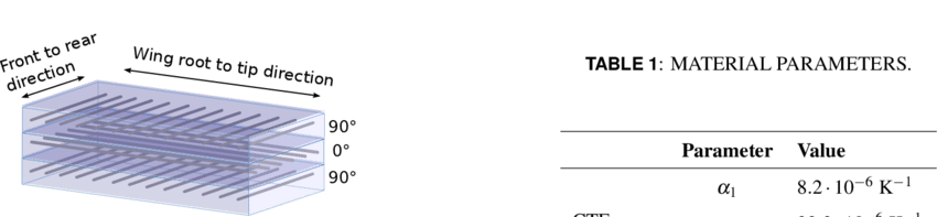
SHEMATIC PICTURE OF THE LAYUP USED-FOR ALL COMPOSITE PARTS IN THE WING BOX SUBASSEMBLY
Matrix Material’s Fundamental Functions in Composites: Protection, Load Transfer, and Thermal Resistance

The matrix in composites serves several essential functions. It protects the fibers, maintains their proper alignment, and facilitates load transfer between them. Additionally, the matrix helps distribute compressive loads across all fibers in the composite, which is crucial in applications involving press molds and compression tooling.

Unique Materials and Processes

The unique properties of composites, such as a high strength-to-weight ratio and anisotropic behavior, significantly influence the design and engineering of composite components. Processes like thermoforming mold and SymaLITE mould are tailored to meet specific performance requirements by strategically placing and orienting fibers within the matrix.

Advantages of Composites

The use of composites, particularly those produced with LFT molding and D-LFT moulding, across various industries offers benefits like improved performance, weight reduction, and enhanced fuel efficiency. In aerospace, composites make aircraft structures lighter, leading to lower fuel consumption and emissions. In automotive, composites like those using hot compression mold and BMC moulding improve crashworthiness and vehicle performance.

Challenges Associated with Composite Manufacturing

Manufacturing composites presents its own set of challenges, including delamination, quality control, and the need for specialized tools and equipment such as thermoforming tooling and compression molds. To mitigate these challenges, careful design and planning, stringent quality control measures, and proper operator training and education are crucial.

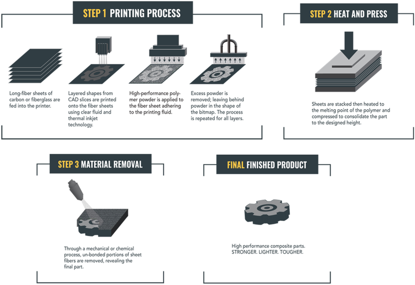
composite compression Manufacturing Process
Conclusion

Understanding the unique properties of composites and their manufacturing processes, including those involving SMC tools and thermoset molds, is crucial for the successful design and engineering of composite components. By leveraging these unique materials and processes, industries can benefit from improved performance, weight reduction, and enhanced fuel efficiency. As the adoption of composites continues to rise, overcoming the challenges associated with manufacturing is essential to unlocking their full potential in various applications.