As urban infrastructure continues to expand worldwide, the demand for safe, durable, and high-load manhole covers is increasing rapidly. At the core of this development lies the manhole cover mould, a precision-engineered tool that directly determines product strength, dimensional accuracy, surface quality, and long-term reliability.
Whether used for composite, FRP, or concrete manhole covers, a high-quality manhole cover mould is essential for meeting modern load standards, improving production efficiency, and reducing lifecycle costs.
What Is a Manhole Cover Mould?
A manhole cover mould is a specialized manufacturing tool designed to form manhole covers under controlled pressure, temperature, and curing conditions. It defines the final geometry, surface pattern, and structural performance of the cover.
Depending on the material system and production process, manhole cover moulds can be designed for:
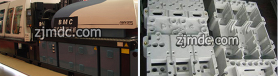
- Composite manhole covers (SMC, BMC, FRP)
- Polymer concrete manhole covers
- Traditional concrete manhole covers

Market Shift Toward Composite Manhole Covers
Traditional cast iron and concrete manhole covers are increasingly being replaced by composite alternatives due to several limitations, including heavy weight, corrosion risks, and high transportation costs.
Composite manhole covers manufactured using compression molding offer significant advantages:
- Lightweight with high load-bearing capacity
- Excellent corrosion and chemical resistance
- Non-conductive and anti-theft properties
- Stable quality and repeatable production
To fully realize these benefits, manufacturers rely on precision-engineered composite manhole cover moulds.
Key Design Features of a High-Quality Manhole Cover Mould
1. Load Performance and Structural Integrity
Manhole covers must comply with international standards such as EN124 (A15, B125, C250, D400). A professional manhole cover mould ensures:
- Uniform material flow and thickness distribution
- Reinforced load-bearing zones
- Elimination of internal voids and weak points
2. Surface Texture and Anti-Slip Patterns
Surface design is both a safety and branding element. Advanced manhole cover moulds integrate:
- Anti-slip textures compliant with safety standards
- Customized logos, text, and identification marks
- Durable surface finishes for long-term use
3. Dimensional Accuracy and Interchangeability
High-precision machining ensures consistent dimensions across production batches, enabling:
- Perfect fit between cover and frame
- Easy installation and replacement
- Reduced maintenance costs

Manhole Cover Mould Types and Manufacturing Processes
Compression Moulds for Composite Manhole Covers
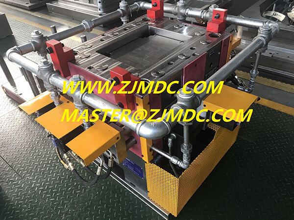
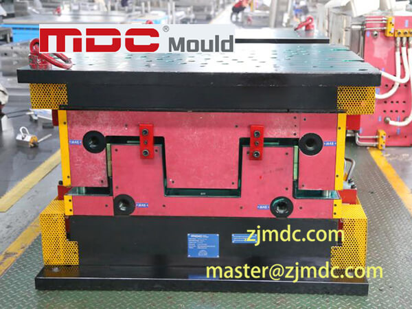
Compression molding is the most widely used process for composite manhole covers. A typical compression manhole cover mould includes:
- Upper and lower mould halves
- Integrated heating systems for controlled curing
- Vent structures to release trapped air
Compression moulds are especially suitable for SMC and BMC materials, offering high productivity and consistent quality.
Concrete and Polymer Concrete Manhole Cover Moulds
Concrete-based manhole cover moulds are designed to withstand:
- Repeated vibration and compaction forces
- Abrasive materials
- Long production cycles
Robust mould structures and wear-resistant materials are essential for extended mould life.
Manufacturing Expertise at MDC Mould
At MDC Mould, we focus on the engineering and manufacturing of high-performance manhole cover moulds for global infrastructure projects.
- High-precision CNC machining
- Optimized mould structure and heat treatment
- Advanced surface texturing technology
- Strict quality inspection and trial production
Each manhole cover mould is developed to ensure stable production, excellent surface quality, and long service life.
Long-Term Value of a Precision Manhole Cover Mould
A well-designed manhole cover mould is a long-term production asset rather than a short-term tool. High-quality moulds deliver:
- Lower defect rates
- Reduced maintenance and downtime
- Stable performance over thousands of cycles
- Lower total manufacturing cost
Conclusion: Precision Tooling Builds Reliable Infrastructure
As infrastructure standards continue to rise, the importance of a reliable and precise manhole cover mould becomes increasingly clear. From composite to concrete applications, mould quality directly defines product performance and lifecycle value.
MDC Mould remains committed to providing professional, durable, and customized manhole cover mould solutions, supporting manufacturers worldwide in building safer and more sustainable infrastructure systems.