As industries continue moving toward lightweight engineering, high-performance composite materials, and sustainable manufacturing, compression molding has become one of the most important production technologies in modern industrial manufacturing.
From automotive composite components and EV battery enclosures to SMC water tanks, aerospace structures, and electrical insulation systems, modern compression molding technology enables the production of strong, lightweight, and corrosion-resistant composite parts.
At Zhejiang MDC Mould Co., Ltd., we specialize in manufacturing advanced:
- SMC molds
- BMC molds
- Compression molds
- Composite tooling
- Carbon fiber molds
- Thermoforming molds
- GMT and LFT tooling systems
Quick Answer:
Compression molding is used to manufacture lightweight, high-strength, heat-resistant, and corrosion-resistant composite parts for industries such as automotive, aerospace, electrical, construction, renewable energy, and medical equipment manufacturing.
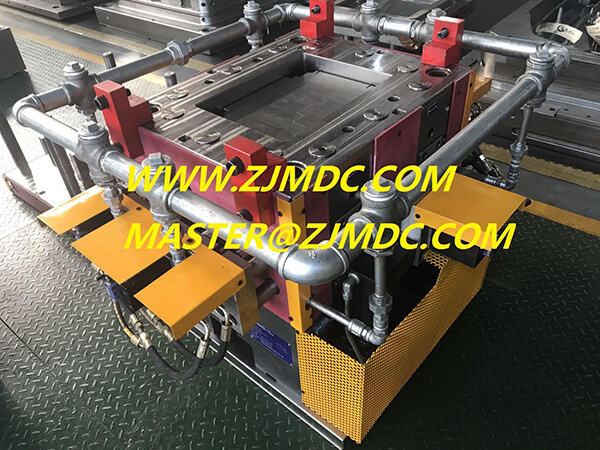
What Is Compression Molding?
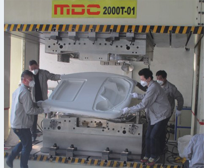
Compression molding is a manufacturing process where composite material is placed into a heated mold cavity and compressed under high pressure to form a finished component.
The process is widely used for:
- SMC molding
- BMC molding
- Carbon fiber molding
- Thermoset composite molding
- Large structural composite panels
- Electrical insulation components
Compared with many traditional plastic molding methods, compression molding provides superior structural strength and excellent dimensional stability for large industrial components.
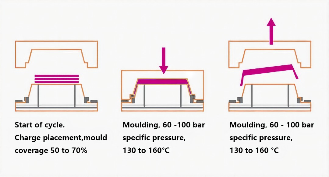
How Does the Compression Molding Process Work?
The standard compression molding process generally includes:
- Preparing composite material charges
- Loading materials into the mold cavity
- Closing the heated compression mold
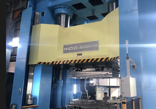
- Applying pressure and temperature
- Curing the composite material
- Opening the mold
- Demolding and trimming the finished product
The process allows the material to flow evenly inside the cavity while achieving high mechanical strength and stable surface quality.
Major Industries Using Compression Molding
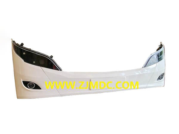
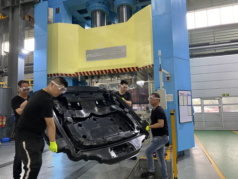
1. Automotive Industry
The automotive sector is one of the largest users of SMC molds and compression tooling.
Compression molded composite parts help manufacturers reduce vehicle weight while improving energy efficiency and structural performance.
Typical Automotive Compression Molded Parts
- EV battery enclosures
- SMC battery covers
- Roof panels
- Truck body components
- Engine splash shields
- Trunk lids
- Automotive exterior panels
- Underbody aerodynamic panels
- Pickup truck cargo systems
As electric vehicles continue expanding globally, lightweight composite manufacturing technologies are becoming increasingly important.
2. Aerospace Industry
The aerospace industry uses advanced carbon fiber molds and composite tooling to manufacture lightweight structures with exceptional strength-to-weight ratios.
- Aircraft cabin panels
- Structural aerospace components
- Satellite composite parts
- Radome systems
- High-temperature resistant panels
Carbon fiber compression molding provides excellent fatigue resistance and dimensional precision for aerospace applications.
3. Electrical & Electronics Industry
BMC molding is widely used in electrical applications because of its excellent insulation and flame resistance.
| Application | Advantages |
|---|---|
| Electrical switch housings | Excellent insulation performance |
| Motor components | Heat resistance |
| Transformer insulation systems | Dimensional stability |
| Circuit breaker parts | Flame retardant properties |
4. Construction & Infrastructure
Compression molding is widely used for manufacturing corrosion-resistant construction products such as:
- SMC water tank panels
- GRP sectional tanks
- FRP water tanks
- Composite ceiling systems
- Architectural composite panels
- Industrial access covers
Compared with steel materials, composite structures provide:
- Longer service life
- Lower maintenance costs
- Better corrosion resistance
- Lightweight installation advantages
5. Medical Equipment Manufacturing
Medical industries increasingly adopt precision compression molds for lightweight equipment housings and structural components.
- MRI machine covers
- Medical device enclosures
- Radiation-resistant panels
- Hospital electrical systems
- Clean-room compatible structures
6. Renewable Energy Applications
Renewable energy systems require lightweight and weather-resistant composite structures.
Compression molded components are widely used in:
- Wind turbine systems
- Solar equipment structures
- Energy storage enclosures
- Industrial composite covers
Common Materials Used in Compression Molding
Modern composite molding technologies support various advanced materials:
- SMC (Sheet Molding Compound)
- BMC (Bulk Molding Compound)
- Carbon fiber composites
- Glass fiber reinforced plastics
- GMT materials
- LFT materials
- D-LFT composite systems
Advantages of Compression Molding
Main Benefits of Compression Molding
- Excellent strength-to-weight ratio
- High dimensional stability
- Suitable for large structural components
- Excellent corrosion resistance
- Reduced material waste
- Lower tooling cost for large parts
- High production efficiency
- Excellent surface quality
- Strong electrical insulation performance
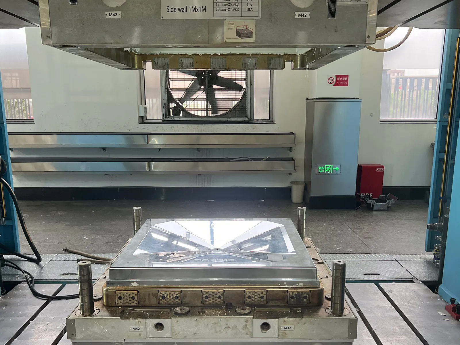
Why High-Precision Compression Tooling Is Important
The performance of composite products heavily depends on the quality of the mold itself.
High-precision compression tooling ensures:
- Stable curing conditions
- Accurate dimensions
- Improved material flow
- Reduced production defects
- Longer mold lifespan
- Better demolding performance
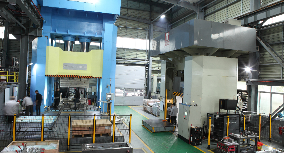
At MDC Mould, advanced CNC machining, precision polishing, and CAE analysis technologies are used to manufacture high-performance composite molds for global customers.
Future Trends of Compression Molding
The future of compression molding technology is closely linked with:
- Electric vehicle lightweighting
- Carbon fiber industrialization
- Large integrated composite structures
- Sustainable manufacturing systems
- Automated molding production lines
- Advanced thermoset composite technologies
As global industries continue demanding stronger and lighter materials, advanced composite molding solutions will continue expanding rapidly.
Why Choose MDC Mould?
MDC Mould specializes in:
- SMC mold manufacturing
- BMC mold manufacturing
- Compression tooling systems
- Carbon fiber molds
- Composite tooling solutions
- Thermoforming molds
- Automotive composite molds
Our engineering capabilities include:
- CAE mold flow analysis
- Precision CNC machining
- Mirror surface polishing
- Large-scale mold assembly
- Composite product development support
- Global technical cooperation
Conclusion
Compression molding is widely used in automotive, aerospace, electrical, construction, medical, and renewable energy industries because it enables the production of lightweight, durable, and high-performance composite parts.
With the rapid development of electric vehicles, sustainable manufacturing, and advanced composite materials, the demand for high-quality compression molds and composite tooling will continue growing globally.
As a professional manufacturer of SMC molds, BMC molds, and advanced compression tooling, MDC Mould continues supporting customers worldwide with high-precision composite manufacturing solutions.