The successful advancement of the Artemis II mission by NASA marks a new era in human space exploration. As the first crewed mission to orbit the Moon in over 50 years, Artemis II is not only a milestone in aerospace engineering but also a powerful signal of technological evolution across the entire manufacturing ecosystem.
Behind every aerospace breakthrough lies a foundation of high-precision tooling, advanced composite molds, and sophisticated manufacturing processes. For companies like Zhejiang MDC Mould Co., Ltd. (MDC Mould), the rapid development of aerospace technologies is creating unprecedented opportunities and technical demands in the field of composite mold manufacturing.
This article explores how aerospace programs such as Artemis II are reshaping the requirements for SMC molds, compression molds, and composite tooling, and how advanced mold manufacturers are adapting to meet the stringent standards of the aerospace industry.
1. Aerospace Innovation and the Rise of Advanced Composite Materials
Modern aerospace systems rely heavily on lightweight, high-strength composite materials to achieve performance, fuel efficiency, and structural integrity. In missions like Artemis II, components must withstand:
- Extreme temperature fluctuations
- High mechanical stress and vibration
- Radiation exposure in deep space
- Strict weight limitations for launch efficiency
To meet these requirements, aerospace manufacturers increasingly utilize:
- Carbon fiber reinforced polymers (CFRP)
- Glass fiber reinforced polymers (GFRP / GRP)
- Sheet Molding Compound (SMC)
- Bulk Molding Compound (BMC)
These materials require highly specialized composite molds and compression tooling to ensure dimensional accuracy, surface quality, and repeatability.
2. The Critical Role of Composite Molds in Aerospace Manufacturing
In aerospace applications, the margin for error is virtually zero. Every component must meet strict tolerances and performance standards. This makes high-precision mold design and manufacturing a critical factor in the success of aerospace programs.
Key requirements for aerospace-grade molds include:
- Ultra-high dimensional accuracy (micron-level precision)
- Excellent thermal stability under high curing temperatures
- Uniform pressure distribution in compression molding
- Superior surface finish for aerodynamic performance
- Long mold life under high production cycles
At MDC Mould, advanced SMC mold and compression tooling solutions are engineered to meet these requirements, supporting industries that demand aerospace-level quality standards.

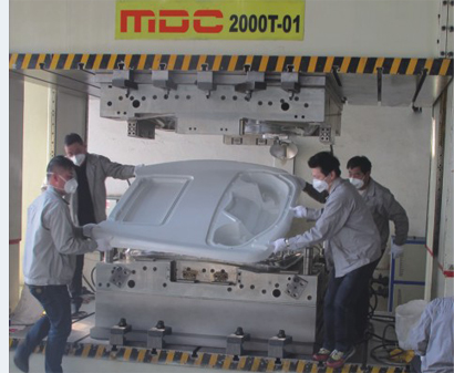
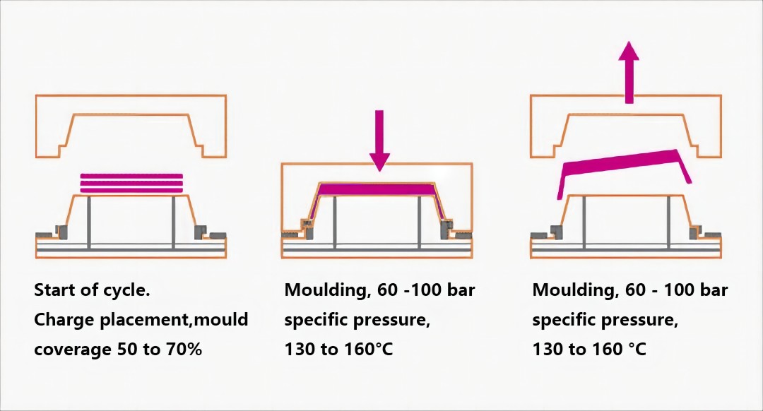
3. Compression Molding Technology in Aerospace Components
Compression molding has become one of the most important processes for manufacturing composite aerospace components. It allows for:
- High-volume production with consistent quality
- Complex geometries with integrated structural features
- Reduced material waste compared to traditional machining
- Excellent surface finish (Class A surfaces)
In aerospace and related industries, SMC molds, BMC molds, and carbon fiber molds are widely used for:
- Interior structural panels
- Lightweight enclosures and housings
- Thermal protection components
- Electrical insulation systems
The same technologies are also increasingly applied in automotive lightweighting, EV battery enclosures, and high-end industrial applications, demonstrating the cross-industry impact of aerospace innovation.
4. How Artemis II Drives New Standards for Mold Manufacturing
The technological requirements of missions like Artemis II are pushing the entire supply chain—including mold manufacturers—to adopt higher standards in:
- Material selection: High-performance tool steels and composite-compatible surfaces
- CNC machining: Multi-axis precision machining for complex mold geometries
- Surface treatment: Advanced coatings for durability and release performance
- Process simulation: Digital modeling of pressure, temperature, and material flow
At MDC Mould, the integration of high-speed CNC machining, precision polishing, and advanced mold testing systems ensures that every mold meets international quality standards required by demanding industries such as aerospace and automotive.
5. Lightweight Engineering and the Future of Tooling
One of the core objectives of Artemis II and future space missions is weight reduction without compromising strength. This concept is directly influencing mold design and composite manufacturing.
Modern tooling must support:
- Thin-wall composite structures
- Integrated functional designs (reducing assembly steps)
- Hybrid material systems (metal + composite)
This requires mold manufacturers to have deep expertise in:
- Material behavior during curing
- Thermal expansion control
- Precision alignment systems
- Vacuum and pressure-assisted molding technologies
6. MDC Mould’s Role in the Advanced Composite Tooling Industry
As a professional manufacturer of SMC molds, compression molds, and composite tooling, MDC Mould is positioned at the forefront of this technological transformation.
With extensive experience in:
- Automotive lightweight components
- EV battery enclosure molds
- SMC water tank molds and panels
- Industrial composite applications
MDC Mould applies aerospace-level precision and engineering principles to deliver:
- High-performance composite molds
- Optimized compression tooling solutions
- Reliable production consistency
- Cost-effective manufacturing efficiency

7. Future Outlook: Aerospace Trends Shaping Mold Manufacturing
Looking ahead, the continued development of space exploration programs such as Artemis II will accelerate innovation in:
- Advanced composite materials
- Automation and smart manufacturing
- Digital twin and simulation technologies
- Sustainable and recyclable composite systems
Mold manufacturers who invest in these technologies will be better positioned to support the next generation of aerospace and high-performance industrial applications.
Conclusion
From the launchpad of Artemis II to the precision workshops of advanced mold manufacturers, aerospace innovation is transforming the way high-performance components are designed and produced.
For companies like MDC Mould, this represents not only a challenge but also a significant opportunity—to deliver world-class composite molds, SMC tooling, and compression mold solutions that meet the evolving demands of global industries.
As aerospace technology continues to push the boundaries of engineering, the role of precision mold manufacturing will remain a cornerstone of innovation, enabling the future of lightweight, high-strength, and high-efficiency composite structures.
FAQ
What is an aerospace composite mold?
A high-precision mold used to manufacture composite aerospace components.
Why is compression molding important?
It ensures high strength, consistency, and efficiency.
What materials are used?
Carbon fiber, glass fiber, SMC, and BMC.